Compare Model Drawings, CAD & Specs Optic Diameter Adjustment Screw Thread Optic Loading Material Special Features Availability Price
$203
In Stock
12.7 mm 80 TPI Front Stainless Steel
In Stock
$203
3 Weeks
12.7 mm 80 TPI Rear Stainless Steel
3 Weeks
$160
In Stock
19.1 mm 100 TPI Front Anodized Aluminum
In Stock
$160
In Stock
19.1 mm 100 TPI Rear Anodized Aluminum
In Stock
$168
In Stock
19.1 mm 100 TPI Rear Anodized Aluminum Threaded Aperture
In Stock
$160
In Stock
20 mm 100 TPI Rear Anodized Aluminum
In Stock
$160
In Stock
20 mm 100 TPI Rear Anodized Aluminum
In Stock
$168
In Stock
20 mm 100 TPI Rear Anodized Aluminum Threaded Aperture
In Stock
$193
In Stock
25.4 mm 80 TPI Front Anodized Aluminum
In Stock
$193
In Stock
25.4 mm 80 TPI Front Anodized Aluminum
In Stock
$206
In Stock
25.4 mm 80 TPI Rear Anodized Aluminum Threaded Aperture
In Stock
$254
In Stock
25.4 mm 100 TPI Front Anodized Aluminum Low-Stress Mounting
In Stock
$254
In Stock
25.4 mm 100 TPI Front Anodized Aluminum Low-Stress Mounting
In Stock
$223
In Stock
25.4 mm 100 TPI Front Stainless Steel
In Stock
$223
25.4 mm 100 TPI Rear Stainless Steel
$235
25.4 mm 100 TPI Rear Stainless Steel Threaded Aperture
$241
1 Week
25.4 mm 100 TPI Front Stainless Steel Low-Stress Mounting
1 Week
$248
In Stock
50.8 mm 80 TPI Front Anodized Aluminum
In Stock
$258
In Stock
50.8 mm 80 TPI Rear Anodized Aluminum Threaded Aperture
In Stock

Specifications

  • Mechanism
    Kinematic
  • Actuator Drive
    Hex Key
  • Actuator Locks
    Yes
  • Adjustments
    θx, θy

Features

Keep Your Hands Out of Harms Way

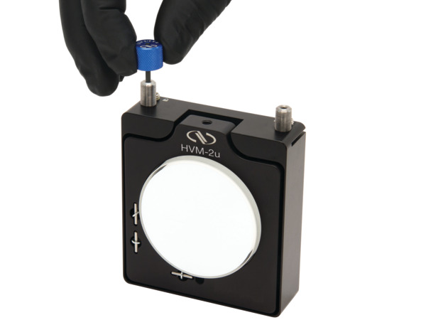
Top adjust mounts have their adjustment screws located above where the optic is held so that your hands never have to cross into the beam path area.

Compact Geometry
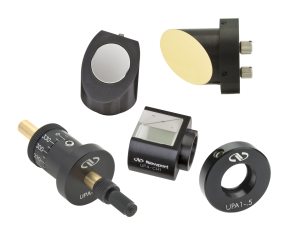
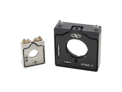
Top adjust mirror mounts feature a slimmer profile and smaller footprint than traditional mounts. As such, they can often fit more easily into tight or restricted spaces when traditional mounts may not. Top adjust mirror mounts are ideal for use in laser cavities, OEM, and industrial applications due to their exceptionally slim profile and accessible actuators.
Locking Allen-Key Adjusters

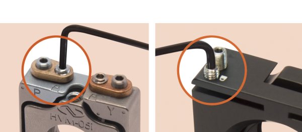
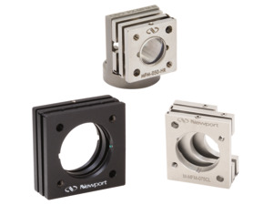
All of Newport's industrial top adjust mounts have locking Allen-Key adjustments to save space and prevent unintended adjustment. Among them, all aluminum mounts have a flexure lock built into the mount body, and stainless steel mounts feature a lever lock. Both types of locks exert a tangential force on the screw to prevent rotation. Adjustment and locking actions are accomplished using a single tool from the same side of the mount.

Left: Lever lock. Right: Flexure lock built into the mount body.

Alignment Pin Holes

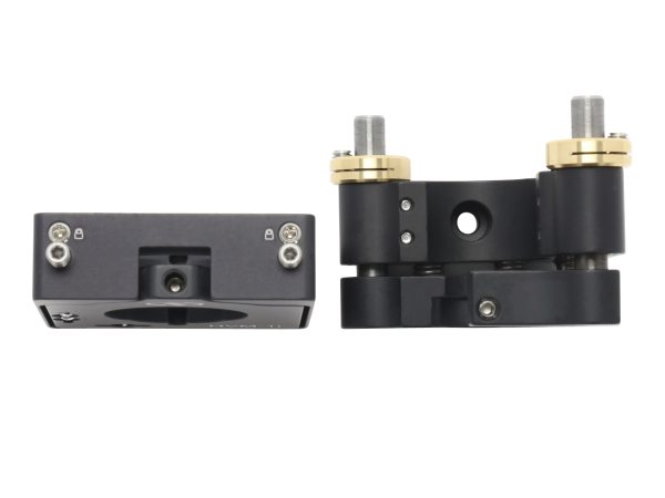
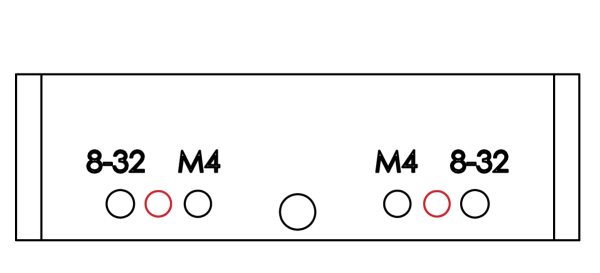
These mounts feature alignment pin holes (illustrated in red) on the bottom (base) of the mount to enable keying of the position and orientation by means of dowel pins for repeatable system integration and to prevent clocking effects. (Note: Dowel pins not included with mount.) This is especially helpful in OEM applications.

Threaded Aperture Mounts for Thin Optic

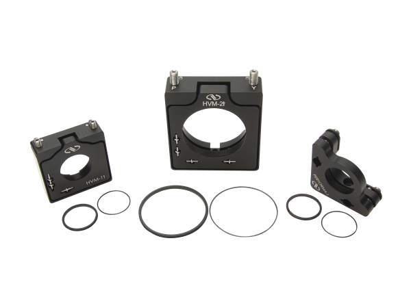
The HVM-1t, HVM-S1t, HVM-2t top adjust threaded aperture mounts are designed to hold thin optics and lenses with a threaded retainer. They include not only a threaded retaining ring but also a protective Delrin spacer to prevent scratching the optic's coating or surface as it is secured. Vacuum pick-up tools and spanner wrench facilitate installation and removal of the optic.

HVM-1t, HMV-2t, P100-At28

3-Point Mounting for Low Wavefront Distortion

The HVM-S1w, HVM-1lt and M- HVM-1lt top adjust mounts are designed to hold 1 in. optics with a 3-point mounting fixture for reduced wavefront distortion. Because there are twice as many mounting points, the forces that would cause distortion are essentially cut in half, more distributed, and axially opposite to eliminate bending.

Rear-Loading Keeps Optic Surface in Consistent Location

Both the HVM-05r, HVM-S1r rear load mounts and HVM-1t, HVM-S1t, HVM-2t threaded aperture mounts feature rear-loading design to ensure that the front surface of the optic would be in the same mounting location regardless of its thickness. In contrast, a front-loading mount would locate a thin optic recessed within the mount thereby limiting its reflective clear aperture. 

Left: Front-Load; Right: Rear-Load

Collection of OEM Mirror Mounts

The newest and best performing OEM mirror mounts come from Newport. We've focused on incorporating key features for industrial applications into each mount including alignment pin slots, adhesive wells and actuator locks.  Click the video link here to see the industry's most cost-effective, compact, and stable mirror mounts.

Purpose:
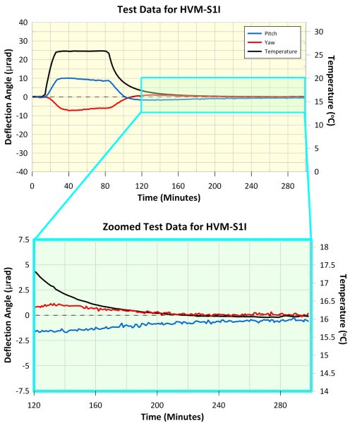
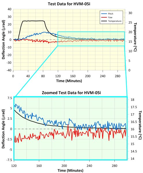
Newport's thermal drift testing of mirror mounts has two purposes: (1) to measure the maximum deflection during a peak temperature shift (after a soaking period) and (2) to measure the shift in position after temperature cycling and return to initial temperature.

Method:
A mirror mount, with mirror installed, was securely fixed to a 1.5"-diameter solid steel pedestal post. This assembly was then placed inside of a climate-controlled environmental chamber and mounted to a stainless steel optical table.  Upon fastening to the table, the mirror mount was set to nominal and zeroed to set the initial position. Throughout the test, an independently thermally isolated CONEX-LDS Autocollimator was used to monitor the reflected beam position. After initial alignment adjustments, the mirror mount was left to rest for two hours to allow the internal kinematic forces to reach equilibrium. Then, the mirror mount was subjected to a 10°C increase in temperature for one hour through convection heating. After a thermal soaking period to ensure the mount is sufficiently heated through, the mirror mount was returned to its original temperature, completing a cycle. This temperature cycling process was repeated 10 times over the duration of 62 hours, with deflection during peak temperature and shift after the end of each cycle recorded.

HVM-S1i Thermal Testing Results

The maximum deflection of the HVM-S1i mirror mount during peak temperature was 10 µrad in pitch and 7 µrad in yaw, and the shift in reflected beam position after temperature cycling was < 1 µrad in pitch and < 1 µrad in yaw. This demonstrates the mount's excellent thermal properties. Further details are shown in the accompanying graphs.

HVM-05i Thermal Testing Results

The maximum deflection of the HVM-05i mirror mount during peak temperature was 10 µrad in pitch and 5 µrad in yaw, and the shift in reflected beam position after temperature cycling was < 2 µrad in pitch and < 2 µrad in yaw. This demonstrates the mount's excellent thermal properties. Further details are shown in the accompanying graphs.