Build to Order Transmission Diffraction Gratings
Transmission gratings have specialized uses in spectrometry. Any optical imaging system, such as a camera or telescope, can be converted into a spectrograph by placing a transmission grating in the system, typically in front of the objective lens. Transmission gratings also serve as convenient beamsplitters for monochromatic light sources such as lasers. The efficiency behavior of transmission gratings is simpler than that for reflection gratings, since no metals are present to introduce complicated electromagnetic effects and since the angles of diffraction are usually small. Thus, polarization effects are virtually absent.
- Incident light is normal to the back surface
- Low to medium blaze angles
- Special-quality substrates with AR coating on back face

Master Grating Options
Plane transmission gratings are listed in order of groove frequency. Blaze wavelengths listed are for the first-order Littrow configuration. The maximum ruled area is groove length x ruled width. Click on a Master Grating Code (last 4 digits of a grating's part number) below to view master grating efficiency curves. Use the request a quote to get a quote based on your requirements. For additional diffraction grating options and custom capabilities, please see the Features section.
| Master Grating Code | Grooves per mm | Nominal Blaze Wavelength | Nominal Groove Angle | Maximum Ruled Area (mm) | Request a Quote |
|---|---|---|---|---|---|
| 111R | 720 | 550 nm | 43.1° | 156 x 206 | Quote |
| 132R | 600 | 540 nm | 34° | 102 x 102 | Quote |
| 550R | 600 | 460 nm | 28.7° | 154 x 206 | Quote |
| 560R | 600 | 400 nm | 22° | 154 x 206 | Quote |
| 660R | 600 | 540 nm | 34° | 154 x 206 | Quote |
| 231R | 497 | 650 nm | 34° | 102 x 102 | Quote |
| 676R | 420 | 620 nm | 26.7° | 52 x 52 | Quote |
| 650R | 400 | 460 nm | 18.7° | 154 x 206 | Quote |
| 391R | 360 | 500 nm | 18.2° | 64 x 64 | Quote |
| 775R | 360 | 580 nm | 21° | 102 x 102 | Quote |
| 770R | 300 | 580 nm | 17.45° | 154 x 206 | Quote |
| 806R | 300 | 490 nm | 14.6° | 102 x 128 | Quote |
| 736R | 300 | 725 nm | 22° | 102 x 102 | Quote |
| 801R | 287.2 | 560 nm | 16.2° | 64 x 64 | Quote |
| 630R | 200 | 505 nm | 10° | 102 x 102 | Quote |
| 633R | 200 | 450 nm | 8.95° | 154 x 206 | Quote |
| 760R | 150 | 580 nm | 8.6° | 154 x 206 | Quote |
| 810R | 150 | 725 nm | 10.8° | 154 x 206 | Quote |
| 108R | 100 | 465 nm | 4.6° | 156 x 206 | Quote |
| 755R | 85 | 610 nm | 5.1° | 102 x 102 | Quote |
| 756R | 75 | 490 nm | 3.65° | 102 x 102 | Quote |
| 750R | 75 | 580 nm | 4.3° | 154 x 206 | Quote |
| 751R | 75 | 730 nm | 5.43° | 154 x 206 | Quote |
| 131R | 45 | 500 nm | 2.22° | 64 x 64 | Quote |
| 906R | 35 | 640 nm | 2.2° | 65 x 76 | Quote |
Features
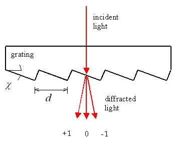
Transmission Grating Geometry
Light incident on a transmission grating is often normal to the back surface of the grating (α = 0; see Fig. 1), in which case the familiar grating equation reduces to
mλ = d sinβ
Here m is the (integral) diffraction order (usually |m| = 2), λ is the wavelength, d the groove spacing and β the angle of diffraction (measured from the normal).
Blazed Transmission Gratings
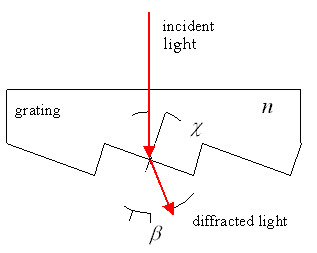
The peak efficiency of a blazed (triangular-groove) transmission grating occurs when the refraction of the incident beam though the mini-prism that constitutes a groove lies in the same direction as the diffraction given by the grating equation. Unlike reflection gratings, the groove angle is much larger than the blaze angle for a transmission grating, since the phase retardation doubles upon reflection but is multiplied by n-1 for a transmission grating, where n is the refractive index of the grating medium.
Applying Snell's law to the interface between the groove facet and air,
n sinχ = sin(χ+β)
Combining this relation with the grating equation, yields the relationship between the blaze angle βB and the groove angle χ:
tanχ = sinββ / (n - cosββ)
For small groove angles and for λ << d, a useful approximation to Eq. (3) relates the blaze wavelength of a reflection grating to that of the corresponding transmission grating. For transmission gratings used in air or vacuum, the ratio of its blaze wavelength (for normal incidence) to that of the equivalent reflection grating (used in Littrow) is
λβ (trans) / λβ (ref) ≈ (n - 1) / 2
where is the blaze wavelength of the corresponding reflection grating. This approximate formula, rarely in error by more than ten percent, simplifies conversion of information in the Grating Catalog from reflection gratings to transmission gratings. Taking n ≈ 1.6, which is true for most transmission gratings, yields
λβ (trans) / λβ (ref) ≈ 0.3
A corollary to this approximation is that, for n ≈ 1.6, the grooves of a transmission grating are about 10/3 times as deep as those of the corresponding reflection grating. For small diffraction angles (i.e., diffraction near the normal), this ratio holds for the angle χ as well.
The choice of groove angle for transmission gratings is limited by total internal reflection effects:
χ ≤ arcsin (1/n)
For n ≈ 1.6, this yields about 40° as the upper limit on χ, though in many cases the effective limit is somewhat lower. This means that transmission gratings cannot be used for high-dispersion applications.
Transmission Grating Efficiency
The shape of an ideal efficiency curve for a blazed transmission grating is the same as for a reflection grating in the scalar region (χ < 8°). Peak efficiency occurs at
λβ = (n - 1) d sinχ
It can be shown that most of the incident light will be diffracted into either the zero order or positive first order if
(λ / (n - 1)) d sinχ > 0.85
very little light will go into the negative first order or higher orders.
Transmission Gratings as Beam Dividers
When the angle between two divided beams is small, transmission gratings serve as ideal beamsplitting elements. Most of the transmitted light will be in the zero and first diffracted order when the grating is used off-blaze, and the ratio of the zero order efficiency to the first order efficiency can be varied over a wide range. For three beams, a symmetrical groove profile is required.
Catalog Part Number System
All standard Richardson gratings have a part number according to the following format:
AA BBB CC DD - EEE x
- AA indicates the type of grating (e.g., diced, plano, grism).
- BBB indicates the size of the grating substrate.
- CC indicates the substrate material
- DD indicates the type of coating
- EEE indicates the master grating groove parameters
- x indicates the master grating type (e.g., ruled, holographic, echelle)
Please see Diffraction Grating Part Number System for additional information.
Standard Substrate Sizes
| Size Code BBB | Substrate Dimensions (mm) | Ruled Area (mm) |
|---|---|---|
| 004 | 30 x 30 x 10 | 26 x 26 |
| 005 | Ø50 x 10 | 30 x 32 |
| 006 | 58 x 58 x 10 | 52 x 52 |
| 008 | Ø80 x 10 | 52 x 52 |
| 009 | 68.6 x 68.6 x 9.1 | 64 x 64 |
| 013 | 90 x 90 x 12 | 84 x 84 |
| 015 | 110 x 110 x 12 | 102 x 102 |
Transmission Grating Substrate Options
| Substrate Material Code CC | Substrate Material |
|---|---|
| BF | Borosilicate float or equivalent |
| BK | BK-7 glass or equivalent |
| FL | Float glass |
| FS | Fused silica or equivalent |
| LE | Low-expansion glass |
| SP | Special glass (unspecified) |
| TB | BK-7, transmission grade |
| TF | Fused silica, transmission grade |
| UL | Corning ULE® glass |
| ZD | Schott Zerodur® |
Custom Diffraction Gratings
Newport is pleased to discuss special and unusual applications that are not addressed by our build to order catalog diffraction gratings. In some instances, none of the hundreds of master gratings we have in stock meet specifications, so a new master may be required. Please see Custom Diffraction Gratings for additional information on our capabilities.
Resources
Resources
Master Gratings vs. Replica Gratings(269.6 kB, PDF) Diffraction Grating Guide Diffraction Grating Physics Diffraction Grating Part Number System Guidelines for Specifying Diffraction Gratings The Blaze Arrow Determination of the Blaze Wavelength Measuring the Efficiency of Diffraction Gratings Scattered Light and Stray Light in Diffraction Gratings Measurement of Polarization-Dependent Loss for Plane Diffraction Gratings Diffraction Gratings - The Crucial Dispersive Component Handling Diffraction Gratings