Scattered Light and Stray Light in Diffraction Gratings
An annoying characteristic of all optical surfaces is their ability to scatter light. This undesirable light is often referred to as stray radiant energy (SRE). When this light reaches the detector of an instrument designed to measure an optical signal, the SRE contributes to the noise of the system. This Technical Note examines the causes of unwanted light from gratings and in spectrometers and describes how these forms of unwanted light are measured.
The terminology of SRE is not standard, so for clarity we refer to unwanted light from the surface of the grating itself as scattered light, and unwanted light reaching the detector of a grating-based instrument as stray light.
Causes of Scattered Light
Consider a diffraction grating consisting of a pattern of grooves whose nominal spacing is d. Scattered light is defined as light leaving the surface of a diffraction grating that does not follow the grating equation for the nominal groove spacing,
This is analogous to the concept of scattered light for a mirror, which is the light leaving its surface that does not follow the law of reflection.
mλ = (sinα + sinβ) / λcosβ
Light can be scattered by a diffraction grating due to a number of causes.
- Surface irregularities in the grating coating. A grating surface that is rough on the scale of the incident wavelength (or somewhat smaller) will cause a small portion of the incident light to be scattered diffusely (i.e., into all directions) with intensity that varies approximately with the inverse fourth power of the wavelength. Surface roughness is due in part to the surface quality of the master grating, either ruled or holographic, since the metal coating of a ruled master, and the photoresist coating of a holographic master, are not perfectly smooth. Moreover, the addition of a reflective coating may contribute to the surface roughness due to the coating’s granular structure. [This is not always true, though: in some cases replicated gratings exhibit lower out-of-plane scatter than do their master gratings.]
- Dust, scratches & pinholes on the surface of the grating. Each speck of dust, tiny scratch, and pinhole void in the surface of a reflection grating will serve as a "scatter center" and cause diffuse scatter. This is evident upon inspecting a grating under a bright light: dust, scratches, pinholes &c are easily visible and bright when looked at from many different angles (hence the diffuse nature of their scattered light).
- Irregularities in the position of the grooves. The presence of spatial frequencies in the groove pattern other than the that of the groove spacing d will give rise to constructive interference of the diffracted light at angles that do not follow the grating equation (1) for the nominal groove spacing d, but for a different spacing d' ≠ d.
- Until the recent advent of interferometric control of ruling engines, mechanically ruled gratings exhibited prominent secondary spectra, called ghosts, due to slight deviations in the placement of its grooves compared with their ideal locations. Ghosts that are close to and symmetric about the parent diffracted line are called Rowland ghosts, due to longer-term periodicities (much larger than the groove spacing), whereas Lyman ghosts are farther from the parent line and are caused by short-term periodicities (on the order of the groove spacing). Both Rowland and Lyman ghosts follow the grating equation, but for spatial frequencies other than 1/d.
- Random (rather than periodic) irregularities in groove placement leads to a faint background between orders, rather than sharp ghosts; this background was observed with green Hg light in early days and therefore called grass.
- Ghosts and grass are in-plane effects (that is, they are seen in and near the dispersion plane) and lead to interorder scatter whose intensity varies roughly with the inverse square of the wavelength. Holographic gratings, whose grooves are formed simultaneously, do not exhibit groove placement irregularities if made properly and therefore have much lower levels of interorder scatter.
- Irregularities in the depth of the grooves. This effect is due to the burnishing process and the elasticity of metal coatings (in the case of ruled master gratings) or to disparities in exposure intensities and developing conditions (in the case of holographic master gratings).
- Spurious fringe patterns due to the recording system. For holographic gratings, care must be taken to suppress all unwanted reflections and scattered light when producing the master grating. Light from optical mounts, for example, may reach the master grating blank during exposure and leave a tell-tale fringe pattern that causes scattered light when the grating is coated with a metal and illuminated. A scratch on a lens in a recording beam can create a Fresnel "bulls-eye" pattern on the master grating that serves as a scatter center for every replica made from that master.
Thus, a perfect grating (from the perspective of scattered light) would have a pattern of perfectly placed grooves, each of the proper depth, and the surface irregularities on the grooves would be much smaller than the wavelength of incident light. In such a case, all light incident on the grating would leave according to the grating equation (for the nominal groove spacing d). It is an underappreciated fact that even a perfect grating will have some of its incident light diffracted into unwanted orders (the zero order – specular reflection – always exists, and other orders often exist), which will lead to complications when we consider instrumental stray light.
Measuring Scattered Light from a Grating
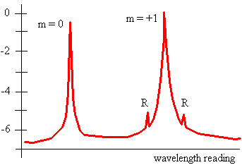
Grating scatter is usually measured in a sensitive monochromator (in which the test grating is the dispersing element) using a narrow-spectral-band source; most commonly used is the green Hg line (λ = 546.1 nm) and the red HeNe line (λ = 632.8 nm). The light is incident on the stationary grating (often converging toward a point behind the grating), and the signal recorded at a detector which is swung about an arc centered at the grating at the focal distance. This procedure generates a scattered light curve such as that shown in Figure 1.
Grating scatter can also be expressed in terms of the bi-directional scatter distribution function (BSDF), in units of inverse steradians, but so far no clear standard method for reporting grating scatter has been adopted.
Causes of Instrumental Stray Light
Consider a spectrometer aligned so that the detector records the analytical wavelength λ in spectral order m. Instrumental stray light is often defined as light of either the wrong wavelength λ' ≠ λ or the wrong spectral order m' ≠ m that reaches the detector. It can be attributed to a number of factors:
- Grating scatter. Light scattered by the grating, as discussed above, may reach the detector and contribute to instrumental stray light. This type of stray light is absent for a "perfect" grating.
- Other diffraction orders. Light of the analytical wavelength λ is not only diffracted into order m, but into any other orders that exist. [The zero order, which always exists but is almost always of no value in the instrument, is particularly troublesome.] The other diffracted beams are not oriented toward the detector but if they reflect off a wall or another optics, or if they scatter off any interior surfaces in the spectrometer, some fraction of their intensity may reach the detector as instrumental stray light. This type of stray light is not absent even for a perfect grating, and requires proper instrumental design (e.g., baffles, light traps, &c.) to reduce.
- Other wavelengths in the same spectral order. Generally, spectrometers use a broad spectral source (e.g., a lamp or discharge tube) and the grating is intended to select a narrow spectral band from the output of the source and diffract it toward the detector. All other wavelengths that leave the source are diffracted as well, unless they are somehow filtered out, and may (if not properly trapped or baffled) reach the detector. In particular, the gratings equation indicates that light of wavelength λ' ≠ λ in order m' ≠ m will be diffracted toward the detector if m'λ' ≠ mλ.
Since detectors are not wavelength-selective (there would be little need for a grating in the system if they were), this energy contributes to instrumental stray light. As with light of the analytical wavelength from other diffraction orders, this type of stray light is not absent for a perfect grating and therefore baffles, light traps and particularly order-sorting filters may be required to reduce its effect.
Thus it is clear that a spectrometer containing a perfect grating (one with no scattered light) will still have nonzero instrumental stray light. The often-made statement "the grating is the greatest cause of stray light in the system" may well be true, but even a perfect grating must obey the grating equation.
Measuring Instrumental Stray Light
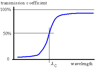
The most common technique for measuring instrumental stray light is by using a set of high-pass cutoff optical filters (whose transmission curve looks like that in Figure 2). The instrument is tuned to the analytical wavelength λ and a series of filters, each with a successively higher λC (>λ), is placed in the beam and intensity readings taken at the detector. [Generally λC should exceed λ by at least 20 nm, in the visible spectrum, to ensure than virtually no light of the analytical wavelength λ passes through the filter and complicates the readings.] Nonzero readings indicate the presence of stray light. A proper study requires measurements at more than one analytical wavelength since stray light properties cannot be extrapolated (due to the different wavelength dependencies of the causes of grating scatter and instrumental stray light noted above, as well as the different efficiency curves in each diffracted order).
Another method is to replace the polychromatic light source with a narrow-band monochromatic light source (Hg lamp, HeNe laser, etc). The instrument is tuned to the peak wavelength of the source and a reading taken. The instrument is then tuned to a different wavelength (beyond the nominal bandpass of the instrument) and another reading taken. Thus stray light can then be expressed as the ratio of the intensities of the scattered light and principal beam.
Often the unwanted light in a spectrometer is quantified not by instrumental stray light but by the signal-to-noise ratio (SNR), a dimensionless quantity of more relevance to instrumental specification. The SNR is defined as the ratio of the signal (light at the detector when the system is oriented for the analytical wavelength) to the noise (the detector reading when a high-pass cutoff filter is used). The inverse of this ratio is sometimes used, in which case the SNR is given in percent transmission; also, the base-ten logarithm of this ratio may be used, in which case the SNR is given in absorbance units.
Ruled and Holographic Diffraction Gratings
The common statement that holographic gratings have lower scatter than ruled gratings is sometimes true but greatly oversimplifies complex phenomena and is not a statement about instrumental performance. Certainly holographic gratings have no measurable ghosts and grass, but they will exhibit scatted light due to surface roughness. Moreover, if in a particular instrument, stray light is due more to the presence of other diffracted orders than to imperfections in the grating itself, then the efficiency curve of the grating in each propagating order will effect stray light readings, and a holographic grating may be less desirable than a ruled grating if its efficiency curves contribute to higher instrumental stray light. The choice of grating type – ruled or holographic – based on stray light considerations is not straightforward, and the best way to make the decision is to take instrumental stray light measurements using a grating of each type (with the same groove spacing, reflective coating, and peak wavelength) in the system.