Build to Order Concave Holographic Diffraction Gratings
Concave holographic gratings function as both a dispersing and focusing element in monochromators and spectrographs. These gratings contain two focusing elements: the substrate, and the groove curvature. As a result, an instrument designer can replace a lens system by using concave gratings, leading to a reduction of optics in a system, and thus, cost. Another advantage of a system based on concave gratings is decreased optical aberrations such as coma and astigmatism. Concave holographic gratings make possible short radii gratings with low ƒ/# and flat-field imaging suitable for array spectrographs.
- Works as both a dispersing and focusing element
- Reduced astigmatism in flat-field spectrographs
- High spectral imaging resolution in Rowland Circle spectrographs
- Reduced astigmatism in constant-deviation monochromators

Concave holographic gratings for are listed below in increasing groove frequency (grooves per mm) for several applications. Click on a Catalog Number to view grating efficiency curves. Request a quote by clicking the quote link. For the gratings listed in this table, the figure at left defines the following parameters:
- α – incidence angle
- r – distance from entrance slit to grating center
- β – diffraction angle
- r' – distance from grating center to image
The angles α and β are measured from the grating normal; their algebraic signs are opposite if they lie on opposite sides of the normal.
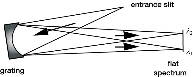
Master Grating Options for Flat-Field Spectrographs
By suitably curving the grooves on the grating, usually by holographic means, adequate spectral resolution can be achieved on a line instead of a circle. This lends itself naturally to use with linear or area detector arrays. While astigmatism is reduced, which increases throughput, the resolution of a flat-field spectrograph is never as great as for a Rowland Circle spectrograph. The advantage of flat-field spectrographs lies in achieving compact spectrometers with no moving parts.
| Catalog Number | Grooves per mm | Imaging Range mλ1, mλ2 (nm) | Reciprocal Linear Dispersion (nm/mm) | Entrance Slit r and α (mm, deg) | λ1 focus r' and β (mm, deg) | λ2 focus r' and β (mm, deg) | Input f/no | Ruled Area (mm) | Substrate Size (mm) | Request a Quote |
|---|---|---|---|---|---|---|---|---|---|---|
| 52056BK-*-028C | 200 | 290-1020 | 32.3 | 151, 5.0 | 153,2,-8.3 | 153,2,-17.0 | 3.5 | Φ44 | Φ50 | Quote |
| 52A16BK-*-307C | 230 | 380-1080 | 31.2 | 137.4, -5.73 | 138.3,10.8 | 134.5,20.4 | 2.0 | Φ68 | Φ69.9 | Quote |
| 52066BK-*-018C | 233.9 | 190-400 | 33 | 148, 3.0 | 116-5.6 | 113, -8.4 | 2.5 | Φ60 | Φ63.5 | Quote |
| 52A15BK-*-224C | 278.3 | 350-1050 | 30 | 88.0, 6.37 | 118.14, -12.02 | 111.13, -23.77 | 2.5 | Φ40 | Φ45 | Quote |
| 52067BK-*-040C† | 282.7 | 190-545 545-900 |
14.5 | 235, -5.3 252, 0.4 |
219, 8.4 | 228, 14.3 | 3.9 4.2 |
Φ60 | Φ63.5 | Quote |
| 52104BF-*-216C | 310 | 470-680 | 33 | 100.9, -5.22 | 101, 13.7 | 101.7, 17.6 | 3.3 | Φ32 | Φ35 | Quote |
| 52146BK-*-332C | 318 | 380-720 | 78.2 | 40.307, -2 | 41.86, 9.348 | 43.56, 15.737 | 1.5 | Φ26 | Φ28 | Quote |
| 52A14BK-*-221C | 367.43 | 200-800 | 25.7 | 88.00, 7.03 | 104.91, -11.29 | 97.90, -24.60 | 2.5 | Φ40 | Φ45 | Quote |
| 52A14BK-*-234C | 367.43 | 200-850 | 25.7 | 88.00, 7.03 | 104.91, -11.29 | 97.90, -24.60 | 2.5 | Φ40 | Φ45 | Quote |
| 52A25BK-*-255C | 400 | 380-730 | 83 | 30, -5.66 | 31.96, 14.52 | 34.19, 23 | 1.2 | Φ24 | Φ26 | Quote |
| 52A16BK-*-324C | 405 | 380-780 | 31.2 | 137.4, -5.73 | 137, 14.7 | 129.8, 24.6 | 2.0 | Φ68 | Φ69.9 | Quote |
| 52097BK-*-207C | 430 | 250-800 | 24.9 | 86.4, 6.0 | 88.6, -12.24 | 85.4, -26.6 | 2.9 | Φ35 | Φ37 | Quote |
| 52097BK-*-208C | 430 | 450-850 | 24.9 | 86.4, 6.0 | 85.4, 17.3 | 83.6, 28.0 | 2.9 | Φ35 | Φ37 | Quote |
| 52097BK-*-209C | 430 | 300-850 | 24.9 | 86.4, 6.0 | 86.1, 13.5 | 83.6, 28.0 | 2.9 | Φ35 | Φ37 | Quote |
| 52112BK-*-261C | 432 | 190-840 | 26.15 | 86.4, 6.0 | 89.4, -10.7 | 85.4, -26.7 | 3.6 | Φ24 | Φ25 | Quote |
| 52107BK-*-214C | 435.9 | 190-680 | 19.5 | 111.48, 5.5 | 111.64, -11.82 | 108.25, -22.45 | 2.2 | Φ51 | Φ55 | Quote |
| 52057BK-*-014C | 435.9 | 190-400 | 19.5 | 109, -6.1 | 114, 10.9 | 113, 16.3 | 2.3 | Φ47 | Φ50.8 | Quote |
| 52066BK-*-001C | 454.27 | 285-720 | 17 | 130, 11.3 | 130, -3.8 | 128, 7.36 | 2.2 | Φ58 | Φ63.5 | Quote |
| 52101BF-*-212C | 477 | 200-850 | 31 | 86.9, -6.7 | 60.9, 12.2 | 70.3, 30.8 | 3.5 | Φ19 | Φ20 | Quote |
| 52101BK-*-211C | 477 | 200-850 | 31 | 86.9, -6.7 | 60.9, 12.2 | 70.3, 30.8 | 3.5 | Φ19 | Φ20 | Quote |
| 52114BK-*-323C | 489.87 | 200-800 | 24 | 77.36, 6.65 | 66.98, -12.35 | 78.0, -30.52 | 2.4 | 28 x 28 | 30 x 30 | Quote |
| 52099BK-*-317CL | 580 | 340-800 | 16 | 98.2, 0.00 | 100.5, 11.37 | 100.8, 29.54 | 3.5 | 37 x 27 | 40 x 30 | Quote |
| 52129BK-*-358C | 586.23 | 340-800 | 19.8 | 90.8, -10.78 | 74.9, 22.7 | 74.0, 41.0 | 3.2 | 28 x 28 | 37 x 37 | Quote |
| 52105BF-*-198C | 660 | 340-805 | 10.1 | 112.5, 4.9 | 122.3, -18.0 | 133.7, -38.0 | 3.0 | Φ38 | Φ40 | Quote |
| 52034BK-*-004C | 664 | 340-700 | 18 | 80, -13.3 | 80, 0.2 | 84, -13.6 | 2.7 | Φ29 | Φ32 | Quote |
| 52001BK-*-021C | 792.8 | 380-780 | 4.5 | 231, 3.0 | 223, 14.4 | 258, 34.5 | 2.4 | Φ95 | Φ100 | Quote |
| 52140BK-*-279C | 800 | 325-800 | 10.7 | 86.3, 0 | 85, 18.2 | 104.5, 43.82 | 2.7 | 28 x 28 | 30 x 30 | Quote |
| 52066BK-*-002C | 813.5 | 380-705 | 9.5 | 130, 22.3 | 128, -4.0 | 129, 11.2 | 2.2 | Φ60 | Φ63.5 | Quote |
| 52049BK-*-012C | 1300 | 340-650 | 7.8 | 94, -31.1 | 99, 4.3 | 97, -19.1 | 2.9 | Φ38 | Φ42 | Quote |
| 52064BK-*-008C | 1803.8 | 753-784 | 1.2 | 345, 67.5 | 387, -25.8 | 394, -29.4 | 6.3 | 50 x 50 | Φ62.5 | Quote |
| 52071BK-*-007C | 2197 | 277-313 | 1 | 575, 4.9 | 288, -43.9 | 296, -50.6 | 10.5 | Φ55 | Φ70 | Quote |
| † This flat-field spectrograph grating is designed to produce two aberration-corrected spectra in the same place (using different entrance slit locations). | ||||||||||
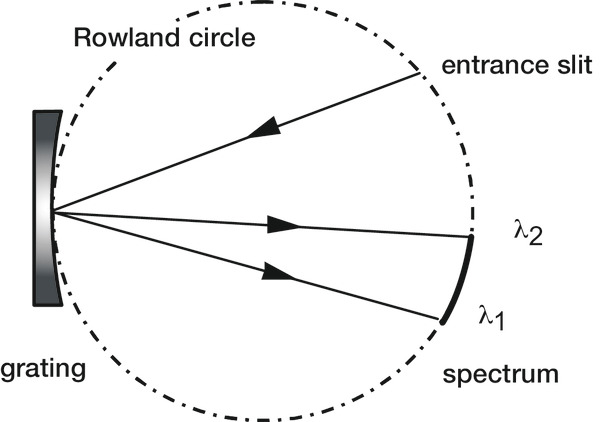
Master Grating Options for Rowland Circle Spectrographs
A "classical" concave grating (one whose grooves are straight, parallel and equally spaced) can be generated on a ruling engine or by recording a laser interference pattern in photoresist (to form a holographic grating). If the object (e.g., entrance slit or fiber) is placed on the Rowland circle (whose diameter equals the radius of curvature of the grating blank), high spectral imaging resolution is obtained.
The detectors or output fibers must be located on the Rowland circle, since that is where the slit images are focused. While the images are narrow in the spectral direction, they suffer from a large amount of astigmatism inherent in this type of grating system.
| Catalog Number | Grooves per mm | Concave Radius (mm) | Recommended Spectral Region | Ruled Area (mm) | Substrate Size (mm) | Request a Quote |
|---|---|---|---|---|---|---|
| 52102BF-*-315C | 390 | 350 | 300 nm-1 μm | Φ48 | Φ50.8 | Quote |
| 52102BF-*-316C | 390 | 350 | 300 nm-1 μm | Φ48 | Φ50.8 | Quote |
| 52088BK-*-257C | 678 | 83.7 | 200 nm-800 nm | Φ32 | Φ38 | Quote |
| 52A02BF-*-356C | 900 | 750 | 120 nm-500 nm | Φ75 | Φ80 | Quote |
| 52011BK-*-003C | 1200 | 498.1 | 300 nm-900 nm | Φ60 | Φ63.5 | Quote |
| 52A02BF-*-556C | 1500 | 750 | 120 nm-500 nm | Φ75 | Φ80 | Quote |
| 52071BK-*-025C | 1760 | 352 | 200 nm-1.1 μm | Φ65 | Φ70 | Quote |
| 52017BK-*-009C | 1800 | 750 | 250 nm-900 nm | Φ59 | Φ63.5 | Quote |
| 52021BK-*-032C | 2160 | 998.8 | 210 nm-350 nm | Φ59 | Φ63.5 | Quote |
| 52017BK-*-247C | 2400 | 750 | 200 nm-700 nm | Φ59 | Φ63.5 | Quote |
| 52017BK-*-434C | 2400 | 750 | 200 nm-700 nm | Φ60 | Φ63.5 | Quote |
| 52017BK-*-482C | 2400 | 750 | 150 nm-800 nm | Φ60 | Φ63.5 | Quote |
| 52017BK-*-484C | 2400 | 750 | 150 nm-800 nm | Φ60 | Φ63.5 | Quote |
| 52A23BK-*-375C | 2400 | 398.8 | 200 nm-700 nm | Φ33 | Φ35 | Quote |
| 52017BK-*-520C | 3600 | 750 | 150 nm-500 nm | Φ60 | Φ63.5 | Quote |
| 52011BK-*-521C | 3600 | 498.1 | 150 nm-500 nm | Φ60 | Φ63.5 | Quote |
| 52011BK-*-530C | 3600 | 498.1 | 180 nm-500 nm | Φ60 | Φ63.5 | Quote |
Master Grating Options for Constant-Deviation Monochromators
Curving the grating grooves can also reduce aberrations in monochromators, in which only a small part of the spectrum is viewed at a time; wavelengths are scanned by rotating the grating. Again, astigmatism is usually reduced (though for part of the spectrum only) to increase throughput, but the resolution is less than for a Rowland Circle spectrograph.
| Catalog Number | Grooves per mm | Nominal Blaze Wavelength (1st Order Littrow) | Imaging Range mλ1, mλ2 (nm) | Reciprocal Linear Dispersion (nm/mm) | Entrance Slit r (mm) | Exit Slit r' (mm) | Deviation Angle 2K (deg) | Input f/no | Ruled Area (mm) | Substrate Size (mm) | Request a Quote |
|---|---|---|---|---|---|---|---|---|---|---|---|
| 52073BK-*-037C | 570 | 2 μm | 1100-2500 | 10 | 203.9 | 184.1 | 38 | 2.4 | Φ84 | Φ90 | Quote |
| 52073BK-*-278C | 1140 | 1 μm | 550-1200 | 3 | 201 | 182.7 | 38 | 2.3 | Φ84 | Φ90 | Quote |
| 52094BK-*-096C | 1198 | 300 nm | 200-1000 | 7 | 105 | 100 | 34.7 | 2.5 | 38 x 38 | 42.4 x 42.4 | Quote |
| 52094BK-*-097C | 1198 | 450 nm | 350-1590 | 7 | 105 | 100 | 34.7 | 2.5 | 38 x 38 | 42.4 x 42.4 | Quote |
| 52094BK-*-098C | 1198 | 375 nm | 200-900 | 7 | 105 | 100 | 34.7 | 2.5 | 38 x 38 | 42.4 x 42.4 | Quote |
| 52105BK-*-226C | 1200 | 250 nm | 200-800 | 8.5 | 100 | 94 | 61.6 | 3.6 | Φ36 | Φ40 | Quote |
| 52111BK-*-228C | 1200 | 350 nm | 200-800 | 8.5 | 100 | 94 | 61.6 | 3.1 | 28 x 28 | 32 x 32 | Quote |
| 52085BF-*-249C | 1200 | 250 nm | 200-600 | 7 | 99.3 | 103.5 | 28 | 3.5 | 29 x 29 | 33 x 33 | Quote |
| 52085BF-*-251C | 1200 | 250 nm | 200-600 | 7 | 99.3 | 103.5 | 28 | 3.5 | 29 x 29 | 33 x 33 | Quote |
| 52085BF-*-364C | 1200 | 225 nm | 200-600 | 7 | 99.3 | 103.5 | 28 | 3.5 | 29 x 29 | 33 x 33 | Quote |
| 52085BF-*-433C | 1200 | 225 nm | 200-600 | 7 | 99.3 | 103.5 | 28 | 3.5 | 29 x 29 | 33 x 33 | Quote |
| 52027BK-*-006C | 1200 | 200 nm | 200-800 | 8.5 | 100 | 94 | 61.6 | 3.6 | 30 x 30 | 32 x 32 | Quote |
| 52057BK-*-020C | 1200 | 450 nm | 325-950 | 7 | 91.1 | 117.7 | 51.2 | 2.5 | Φ47 | Φ50.8 | Quote |
| 52057BK-*-022C | 1200 | 350 nm | 325-950 | 7 | 91.1 | 117.7 | 51.2 | 2.5 | Φ47 | Φ50.8 | Quote |
| 52057BK-*-238C | 1200 | 275 nm | 200-800 | 8.5 | 100 | 94 | 61.6 | 2.5 | Φ45 | Φ50.8 | Quote |
| 52052BF-*-023C | 1350 | 250 nm | 190-700 | 8 | 91.3 | 91.3 | 45 | 2.3 | Φ40 | Φ45 | Quote |
| 52093BK-*-095C | 1500 | 250 nm | 200-800 | 8 | 74.73 | 80 | 47.1 | 3.7 | 24 x 24 | 28 x 28 | Quote |
Features
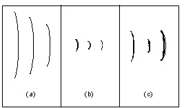
Typical Spectral Images with Concave Holographic Gratings
Concave gratings have an advantage over conventional plane grating systems in that concave gratings perform both imaging as well as dispersion (wavelength separation). This reduces the cost of the optical components in the instrument, reduces alignment time, and perhaps minimizes reflective and refractive energy losses as well. Typical spectral images are shown at three wavelengths from (a) a Rowland Circle spectrograph, (b) a flat-field spectrograph, and (c) a constant-deviation monochromator. Note that resolution (image width) degrades as astigmatism (image height) is reduced.
Catalog Part Number System
All standard Richardson gratings have a part number according to the following format:
AA BBB CC DD - EEE x
- AA indicates the type of grating (e.g., diced, plano, grism).
- BBB indicates the size of the grating substrate.
- CC indicates the substrate material
- DD indicates the type of coating
- EEE indicates the master grating groove parameters
- x indicates the master grating type (e.g., ruled, holographic, echelle)
Please see Diffraction Grating Part Number System for additional information.
Grating Substrate Material Options
The standard substrate material for small and medium-sized gratings is specially annealed borosilicate crown glass. Low expansion material can be supplied on request. Float glass may be used for small, diced gratings. In addition, replicas may be furnished on metal substrates, such as copper or aluminum, for applications with extreme thermal conditions. The substrate material codes CC are given below:
| Substrate Material Code CC | Substrate Material |
|---|---|
| AL | Aluminum |
| BF | Borosilicate float or equivalent |
| BK | BK-7 glass or equivalent |
| CU | Copper |
| FL | Float glass |
| FS | Fused silica or equivalent |
| LE | Low-expansion glass |
| SP | Special glass (unspecified) |
| TB | BK-7, transmission grade |
| TF | Fused silica, transmission grade |
| UL | Corning ULE® glass |
| ZD | Schott Zerodur® |
Diffraction Grating Coating Options
All reflection gratings include a standard aluminum (Al) reflectance coating (Coating Code "01"). Gratings can also be replicated in gold (Au), or overcoated with magnesium fluoride (MgF2) or silver (Ag), to enhance reflectivity in certain spectral regions. The coating material codes DD are shown below:
| Coating Code DD | Coating Material | Application |
|---|---|---|
| 01 | Aluminum (Al) | General purpose applications. |
| 02 | Gold (Au) | Offers higher reflectivity in the infrared. |
| 03 | Magnesium Fluoride (MgF2) | Used to prevent oxidation of aluminum (Al) coatings, which helps maintain high reflectivity in the ultraviolet over time. |
| 06 | Protected Silver (Ag) | Offers higher reflectivity in the visible and near infrared. Silver is protected from tarnishing by a dielectric coating, which helps maintain reflection over time. |
Custom Diffraction Gratings
Newport is pleased to discuss special and unusual applications that are not addressed by our build to order catalog diffraction gratings. In some instances, none of the hundreds of master gratings we have in stock meet specifications, so a new master may be required. Please see Custom Diffraction Gratings for additional information on our capabilities.
Resources
Resources
Master Gratings vs. Replica Gratings(269.6 kB, PDF) Diffraction Grating Guide Diffraction Grating Physics Diffraction Grating Part Number System Guidelines for Specifying Diffraction Gratings The Blaze Arrow Determination of the Blaze Wavelength Measuring the Efficiency of Diffraction Gratings Diffraction Gratings - The Crucial Dispersive Component Scattered Light and Stray Light in Diffraction Gratings Measurement of Polarization-Dependent Loss for Plane Diffraction Gratings Handling Diffraction Gratings