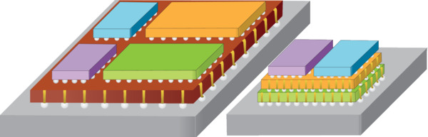
System-in-Package (SiP) Manufacturing
System-in-Package, or SiP, enables heterogeneous integration by placing multiple chips with different functions (memory, logic, sensors) on a single substrate. SiP supports continued system performance increases without relying solely on transistor-level scaling. Laser processing is widely used in SiP for micro-vias, singulation, thinning, and substrate cutting across ceramics, organics, and glass.
Updated: 3/27/2026
SiP Manufacturing Challenges
SiP production requires micrometer accuracy and material-specific processes. Main challenges:
- Micro-via formation
- Diameters from a few microns to ~200 µm.
- Chemical etching works for silicon and some glass, but not for many ceramics or organic laminates.
- Etching adds waste, steps, and cost.
- Material cutting and singulation
- Requires low collateral damage and tight kerf control as feature sizes shrink.
- Thin-material handling
- Non-contact processing reduces mechanical damage and increases yield.
- Material diversity
- Ceramics, ABF, FR4, glass, laminates with embedded copper traces respond differently to mechanical saws, etching, and lasers.

Laser approaches for SiP
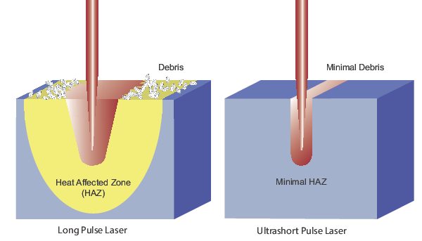
Shorter wavelengths and shorter pulse widths reduce the heat-affected zone, improving precision and yield.
Ultrashort pulse (USP) vs nanosecond (ns) lasers
- Nanosecond lasers
- Good for many singulation and drilling tasks at UV and green wavelengths.
- Higher thermal load can degrade dense layouts.
- Ultrashort pulse (picosecond and femtosecond) lasers
- High peak power induces nonlinear absorption and near-instant material removal.
- Produce negligible HAZ, enabling high-precision drilling and cutting with reduced part failure.
Picosecond Lasers
Typical uses by wavelength:
- UV: micro-vias in ceramic, organic, glass interposers.
- UV and green: ceramic interposer cutting, depaneling, silicon scribing/dicing.
- IR: glass cutting.
IceFyre® Picosecond Lasers: Spectra-Physics IceFyre picosecond lasers set a new standard for picosecond micromachining and can provide the ultimate solutions for SiP manufacturing. The UV version enables premium quality drilling of micro-vias through ceramic, organic and glass interposers. Both the UV and green versions are great for cutting ceramic interposers, depaneling and scribing and dicing silicon dies. Additionally, the IR version can be used to cut glass interposers.
| IceFyre® | ||||
|---|---|---|---|---|
| Wavelengths | UV | Green | IR | 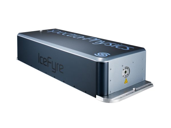 |
| Power | Up to >50 W | |||
| Pulse Width | <12 ps | <15 ps | ||
| Repetition Rates | Single Shot to 10 MHz | |||
| Max Pulse Energy | Up to >40 µJ | Up to >60 µJ | Up to >200 µJ | |
Nanosecond Lasers
Use cases: high-throughput micro-via drilling, interposer cutting, depaneling, scribing/dicing.
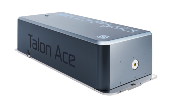
- Talon® Ace™ Lasers: Delivering an industry-leading >100 Watts of UV power, Talon Ace offers the lowest cost-per-Watt and cost of ownership for high power nanosecond UV lasers. This laser can be employed for a whole host of applications including drilling micro-vias through ceramic, organic laminate and glass interposers, cutting ceramic and organic laminate interposers, depaneling, and scribing and dicing dies. Talon Ace also includes our proprietary TimeShift programmable burst-mode technology for the most versatile pulse control, leading to increased process speed and quality.
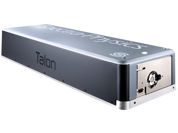
- Talon® Nanosecond Lasers: For the best combination of performance, reliability and cost in SiP laser manufacturing, Spectra-Physics Talon lasers deliver excellent results. Talon works exceptionally well for cutting ceramic and organic laminate interposers, depaneling and scribing and dicing silicon dies. The UV version in particular is also able to drill micro-vias through ceramic and organic interposers. The Talon provides high quality results, but its cuts and drills may not be as pristine as the IceFyre’s. Talon’s advantage over IceFyre, though, is that it can cut and drill faster.
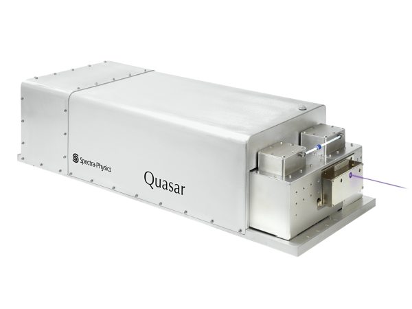
- Quasar® High-Power Nanosecond Lasers: Other lasers highly suited for SiP manufacturing are the Spectra-Physics Quasar® and Talon® Ace nanosecond series of lasers. The Talon Ace UV100 is the highest-powered single mode UV laser in the industry, so it delivers fast micromachining and provides 24/7 industrial reliability. Like the IceFyre and Talon, the UV and green versions of the Quasar and Talon Ace can also be used for depaneling, scribing and dicing dies. And like the UV version of the IceFyre, the Quasar UV and Talon Ace UV can also drill micro-vias through ceramic, organic and glass interposers.
 Talon Ace |
 Talon |
 Quasar |
|
|---|---|---|---|
| Wavelengths | UV | UV or Green | UV or Green |
| Power |
>100 W |
UV: Up to >45 W Green: Up to >40 W |
UV: Up to >80 W Green: Up to >95 W |
| Pulse Width |
<2 to >50 ns |
UV: <25 or 40 ns Green: <25 ns |
<2 to >100 ns |
| Repetition Rates |
Single shot to 5 MHz |
0 to 500 kHz | 0 to 3.5 MHz |
| Max Pulse Energy |
Up to >500 µJ |
UV: Up to >500 µJ Green: Up to 1000 µJ |
UV: Up to >400 µJ Green: Up to >475 µJ |
System-in-Package Laser Selection Guide
Presented here is a summary of recommended MKS lasers for various SiP manufacturing applications. Please use this as a reference guide only, and always contact us to discuss your application and requirements in detail so that we may provide the best solution for you.
| Talon® Ace™ | IceFyre® | Talon® | Quasar® | |||||
|---|---|---|---|---|---|---|---|---|
| UV | UV | Green | IR | UV | Green | UV | Green | |
|
Drilling Ceramic Micro-vias |
✓ | ✓ | ✓ | ✓ | ||||
| Drilling Organic Laminate Micro-vias | ✓ | ✓ | ✓ | ✓ | ||||
| Drilling Glass Micro-vias | ✓ | ✓ | ✓ | |||||
| Cutting Ceramic Interposer | ✓ | ✓ | ✓ | ✓ | ✓ | ✓ | ||
| Cutting Organic Laminate Interposer | ✓ | ✓ | ✓ | ✓ | ||||
| Cutting Glass Interposer | ✓ | |||||||
|
Cutting SiP Package Substrate (Depaneling) |
✓ | ✓ | ✓ | ✓ | ✓ | ✓ | ||
|
Scribing/Dicing* Silicon Die |
✓ | ✓ | ✓ | ✓ | ✓ | ✓ | ✓ | |
* Dicing thin wafers < 100 µm
Laser Beam Beam Measurement and Monitoring
Lasers and optics degrade from thermal effects, contamination, and vibration. Regular monitoring prevents process drift and downtime.
Laser Power Sensors
MKS offers a comprehensive portfolio of Ophir® laser thermal power sensors for pulsed and ultrashort lasers with high damage thresholds and ISO/IEC 17025 calibration.
| F150(200)A-CM-16 | 30(150)A-SV-17 | F80(120)A-CM-17 | ||
|---|---|---|---|---|
| Spectral Range | 0.248-9.4 µm | 0.19-11 µm | 0.248-9.4 µm | 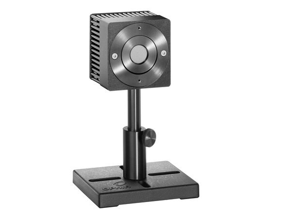 |
| Power Range | 300 mW - 200 W | 100 mW - 150 W | 100 mW - 120 W | |
| Energy Range | 50 mJ – 200 J | 50 mJ – 300 J | 50 mJ – 200 J | |
| Max Avg Power Density | 35 kW/cm2 | 60 kW/cm2 | 35 kW/cm2 | |
| Max Energy Density (2 msec) | 45 J/cm2 | 50 J/cm2 | 45 J/cm2 | |
| Aperture | Ø16 mm | Ø17 mm | Ø17.5 mm | |
| Response Time | 3 sec | 1.7 sec | 2 sec |
Virtual Power Meters and Software
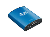
- USB or Ethernet connectivity for sensor networks, remote control, data logging, and analysis.
- Example tools support multiple sensors on a single PC and remote monitoring.
- User-friendly software with extensive graphic displays, advanced measurement processing and data logging.
Beam Profilers
Ophir beam profiling cameras allow real-time viewing and measuring of a laser’s structure in high resolution while also measuring cross-sectional intensity providing a complete 2-dimensional view of the laser mode.
- SP932U Beam Profiling Camera: high resolution, real-time viewing and measuring of laser structure with highest accuracy in the industry
- Pyrocam™ IV Beam Profiling Camera: generates full 2D profiles of CO2 and NIR lasers in CW or pulsed modes of any frequency
- NanoScan™ 2s Pyro/9/5 Scanning-Slit Profiler: sub-micron precision for generating 2 orthogonal linear profiles of a CO2 or IR beam
Industrial Grade Positioners
Micron-level positioning at high speed is essential for SiP throughput and accuracy.
| IDL-LM Series | ||
|---|---|---|
| Travel Range | 100 to 1200 mm | 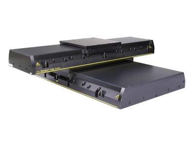 |
| Speed | 2000 mm/s | |
| Load Capacity | 450 to 2,000 N | |
| Accuracy | ±2 to ±5 µm | |
| Repeatability | ±0.25 to ±0.5 µm | |
| Pitch | ±15 to ±65 µrad | |
| Yaw | ±15 to ±40 µrad | |
Motion Controllers
Multi-axis controllers synchronize galvos and stages, provide extensive I/O, and support complex trajectories for industrial production.
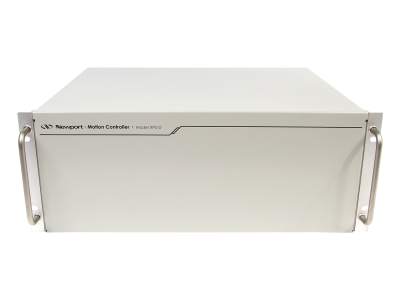 XPS-D |
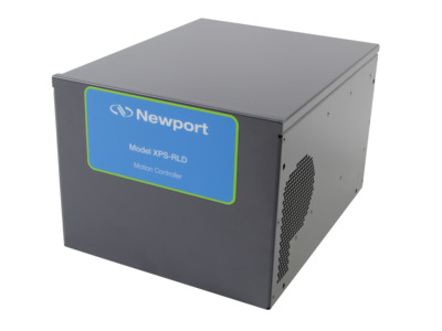 XPS-RLD |
|---|---|
|
|
High-Energy Laser Optics
For the SiP manufacturing lasers required, wavelength-optimized optics (355, 532, 1064 nm) with high LIDT for high-fluence are required.
- High Energy mirrors, lenses, beam splitter cubes, waveplates
- LIDT (Laser Induced Damage Threshold) of Joules and tens of Joules per cm2
CO2 Laser Lenses
For SiP operations that utilize CO2 lasers, Ophir low absorption Zinc Selenide (ZnSe) lenses have transmission above 99% for kW-class lasers, extending lifetime in high-power CO2 setups.
| CO2 Laser Lenses | |||
|---|---|---|---|
| Coating | Duralens™ | Black Magic™ | Clear Magic™ |
| Wavelength | 10.6 µm | ||
| Transmission | >99.3% | >99.35% | >99.37% |
| Absorption | <0.2% | <0.15% | <0.13% |
| Reflection | <0.2% | <0.25% | <0.25% |
| Diameters | 1.1 to 2.5 in. | 1.1 to 2.5 in. | 1.1 to 2.0 in. |
| Shapes | Plano-Convex Meniscus |
||
Opto-Mechanical Components
Stable mounts, mirror holders, lens positioners, and post assemblies reduce drift and maintain beam quality in production environments. Typical materials include stainless steel and aluminum. Components should be designed for vibration resistance and thermal stability.
- Mirror mounts, lens positioners and other optical mounts
- Linear and rotary positioners
- Optical post assemblies
Sip Manufacturing Quick Reference Table
| Issue | Preferred Laser | Positioning | Measurement |
|---|---|---|---|
| Micro-vias in ceramic | UV picosecond or UV ns | Micron stages, synchronized galvo | High-damage-threshold power sensor, beam profiler |
| Thin silicon dicing | UV/green picosecond | High-repeatability linear positioner | In-line power monitoring |
| Glass interposer cutting | IR picosecond | Low-vibration stages | Camera-based profiler or slit profiler |
Resources
Advancing System-in-Package SiP Technology(7.3 MB, PDF)