The Michelson Interferometer Experimental Setup
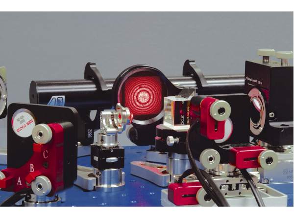
Albert A. Michelson won the 1907 Nobel Prize in Physics for his optical precision instruments and the spectroscopic and metrological investigations carried out with their aid. One of his instruments was the Michelson interferometer. The Michelson interferometer produces interference fringes by splitting a beam of monochromatic light so that one beam strikes a fixed mirror and the other a movable mirror. When the reflected beams are brought back together, an interference pattern results. (See photo below.) Precise distance measurements can be made with the Michelson interferometer by moving the mirror and counting the interference fringes that move by a reference point. The distance d associated with the mth fringe and wavelength l is
For more information see Optics, Second Edition by Eugene Hecht (Addison Wesley Publishing Company, 1987, pp. 354-358), or Optical Electronics, Third Edition by Amnon Yariv (CBS College Publishing, 1985, pp. 335-339) Building a motorized Michelson interferometer experimental setup using our integrated motion-control solutions is straightforward. We offer a variety of motorized components including optical mirror mounts and translation stages. Every component is compatible with each other (and with our plug-&-play driver modules) so that system integration is a snap.
Experimental Setup
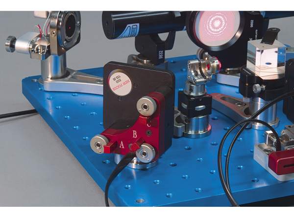
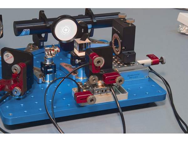
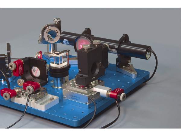
As shown on Triple-Divide™ Translation Stages, light from a HeNe laser is turned by a Model 8817-8-V motorized Stability™ center mount and Model 8809 motorized corner mount, expanded by a Model 5725-H aspheric lens and is split by a 50/50 beamsplitter cube so that the two beams travel different paths. The first travels to the fixed mirror held in the Model 8807 motorized center mount. The second travels to a movable mirror held in a Model 9814-8 top mount on a Model 9067-COM-E 1 in. travel encoded stage. The two beams recombine back in the beamsplitter and the interference pattern is displayed on the screen held in the Model 9852 Opti-Claw™ mount.
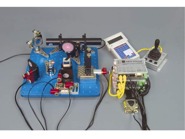
For your convenience, use the Model 8766-KIT six-axis Intelligent Picomotor (iPico™) driver kit. The Model 8766-KIT is equipped with a network controller and two drivers for controlling up to six individual Picomotor actuators (three on the Model 8809 corner mount, two on the Model 8807 mount and one on the Model 9062-X-P stage). It includes a Model 8752 Ethernet controller, a Model 8755 power supply, and two Model 8753 iPico drivers. The kit also includes all required mounting and interface cables to make installation easy. For manual control, add the Model 8754 iPico joystick, or the Model 8757 iPico handpad.