Build to Order Plane Holographic Diffraction Gratings

A holographic diffraction grating has a sinusoidal groove shape, created by recording interference fringe fields in photoresist material. Since the grooves are symmetric, they do not have a preferred blaze direction. The range of useful diffraction efficiency is controlled by varying the modulation (the ratio of groove depth to groove spacing). The lower the modulation, the shorter the wavelength limit to which the grating can be used, but the peak efficiency may be lowered as well. Holographic gratings contain no periodic errors or “ghosts” as they are generated optically.

  • Extremely high diffraction efficiency
  • More accurate periodicity and less ghosting than ruled gratings
  • Special size, substrate and coating options


Build_To_Order_Plane_Holographic_Diffraction_Gratings


View Standard In-stock Plane Holographic Gratings

Master Grating Options

Plane holographic gratings are listed in order of groove frequency, with the lowest blaze angle listed first. Blaze wavelengths listed are for the first-order Littrow configuration. The maximum ruled area is groove length x ruled width. Click on a Master Grating Code (last 4 digits of a grating's part number) below to view master grating efficiency curves. Use the request a quote to get a quote based on your requirements. For additional diffraction grating options and custom capabilities, please see the Features section.

Features

Blazed Holographic Grating Construction

Holographic diffraction gratings typically have a sinusoidal surface profile generated optically by recording an interference pattern onto a photoresist-coated substrate. The photoresist is then coated with a vacuum deposited metal layer to produce a master grating, which may be used as a mold to produce replicated gratings. The final product typically consists of a substrate, a resin bonding layer, a patterned metal reflective layer, and a protective over coating. Holographic blazed gratings are generated by bombarding a holographically produced master with an angled beam of ions to etch the sinusoidal surface profile into a symmetric triangular profile. Holographic gratings are ideal for use in spectroscopy systems requiring very high resolution.

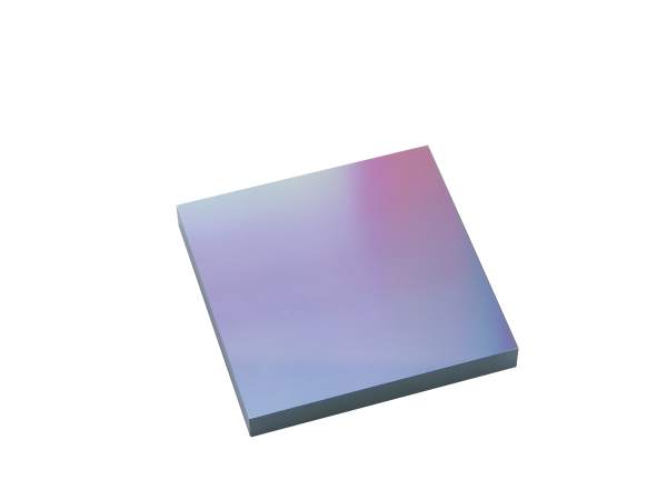
33010-50x50-2
Figure_2-1a_THUMB
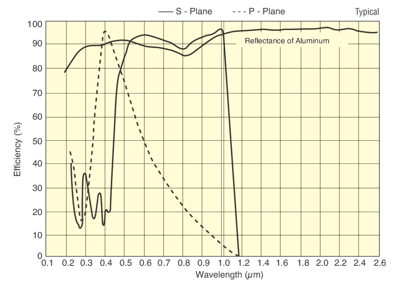
Plane Holographic Reflection Grating, 1800 g/mm, high modulation, 350-900 nm recommended spectral range, aluminum coating

Diffraction Efficiency and Polarization Effects

Holographic diffraction gratings can have very high diffraction efficiency, even above that of flat aluminum reflectors, at the design wavelengths and orientation. Diffraction efficiency is highly dependent on polarization state. Planar holographic gratings typically feature narrower spectral bandwidth, and have their peak efficiency at a shorter wavelength for P-polarization compared to S-polarization. For laser cavity applications this property may be used to feed back light from a specifically chosen wavelength and polarization state back into the laser gain medium to control the output of the laser. Conversely, applications such as spectrometers designed to operate using unpolarized light may require the use two gratings in conjunction with a polarizing beamsplitter to obtain optimum results.

Optimum Grating Orientation

Like their ruled counterparts, holographic gratings are most efficient when used in the Littrow configuration, or aligned so that the diffraction angle of the dominant diffraction order is coincident with the input beam, effectively behaving as a retroreflector at a specific wavelength. This geometry is especially useful for applications using a diffraction grating inside a laser cavity to select a particular wavelength. Only the exact chosen wavelength will reflect into the laser cavity. Holographic gratings are particularly useful because they have peak efficiency only at a particular polarization, allowing them to be used as a substitute for a Brewster window to control the laser output polarization.

Catalog Part Number System

All standard Richardson gratings have a part number according to the following format:

AA BBB CC DD - EEE x

  • AA indicates the type of grating (e.g., diced, plano, grism).
  • BBB indicates the size of the grating substrate.
  • CC indicates the substrate material
  • DD indicates the type of coating
  • EEE indicates the master grating groove parameters
  • x indicates the master grating type (e.g., ruled, holographic, echelle)

Please see Diffraction Grating Part Number System for additional information.

Grating Size Options

Grating size is usually dictated by the desired throughput, which is a function of the source and detector characteristics, the resolution of the optical system, and the required data-acquisition rate. The ruled area of each plane grating is shown in the specification table as the "Maximum Ruled Area" which is the groove length followed by the ruled width (for example, 65 x 75 mm indicates a groove length of 65 mm and a ruled width of 75 mm). This determines the largest size allowed from the size options table below.

The dimensions of the ruled area and the substrate may be altered from the regular catalog sizes at an additional cost. Special elongated grating shapes are available (e.g., for echelles and laser tuning gratings).

Size Code BBB Substrate Dimensions (mm) Ruled Area (mm)
108 16.5 x 58 x 10 12 x 52
004 30 x 30 x 10 26 x 26
066 28.5 x 58 x 10 23 x 52
107 40 x 40 x 10 36 x 36
060 25 x 100 x 16 20 x 96
067 50 x 50 x 10 46 x 46
022 30 x 110 x 16 26 x 102
006 58 x 58 x 10 52 x 52
009 68.6 x 68.6 x 9.1 64 x 64
119 68 x 68 x 6 64 x 64
114 50 x 100 x 16 46 x 96
033 76 x 76 x 16 70 x 70
010 76 x 85 x 16 70 x 79
013 90 x 90 x 16 84 x 84
015 110 x 110 x 16 102 x 102
017 110 x 135 x 25 102 x 128
020 135 x 165 x 30 128 x 154
025 110 x 220 x 30 102 x 204
027 135 x 220 x 35 128 x 204
028 165 x 220 x 35 154 x 206

Grating Substrate Material Options

The standard substrate material for small and medium-sized gratings is specially annealed borosilicate crown glass. Low expansion material can be supplied on request. Float glass may be used for small, diced gratings. In addition, replicas may be furnished on metal substrates, such as copper or aluminum, for applications with extreme thermal conditions. The substrate material codes CC are given below:

Substrate Material Code CC Substrate Material
AL Aluminum
BF Borosilicate float or equivalent
BK BK-7 glass or equivalent
CU Copper
FL Float glass
FS Fused silica or equivalent
LE Low-expansion glass
SP Special glass (unspecified)
TB BK-7, transmission grade
TF Fused silica, transmission grade
UL Corning ULE® glass
ZD Schott Zerodur®

Diffraction Grating Coating Options

All reflection gratings include a standard aluminum (Al) reflectance coating (Coating Code "01"). Gratings can also be replicated in gold (Au), or overcoated with magnesium fluoride (MgF2) or silver (Ag), to enhance reflectivity in certain spectral regions. The coating material codes DD are shown below:

Coating Code DD Coating Material Application
01 Aluminum (Al) General purpose applications.
02 Gold (Au) Offers higher reflectivity in the infrared.
03 Magnesium Fluoride (MgF2) Used to prevent oxidation of aluminum (Al) coatings, which helps maintain high reflectivity in the ultraviolet over time.
06 Protected Silver (Ag) Offers higher reflectivity in the visible and near infrared. Silver is protected from tarnishing by a dielectric coating, which helps maintain reflection over time.

Custom Diffraction Gratings

Newport is pleased to discuss special and unusual applications that are not addressed by our build to order catalog diffraction gratings. In some instances, none of the hundreds of master gratings we have in stock meet specifications, so a new master may be required. Please see Custom Diffraction Gratings for additional information on our capabilities.

Resources

Contact Us illustration

Have questions? Require assistance?

Click below to contact Newport Optical Filters and we'll get back with you shortly.

Contact Us