
Piezo Stack Amplifiers
Piezo Stack Amplifiers
Piezoelectric amplifiers offer precision control for all Newport piezo stack and actuator products. Piezoelectric amplifiers have low noise voltage output ranging from -20V to 130V for precision movements. Amplifiers come in both open-loop and closed-loop versions and are integrated with Pre-amplifier Sensor Identification Chip (SIC) resulting higher position accuracy over alternative designs. For convenient control, an RS232 and USB Interface are included.
- Compact and Easy to Use Amplifiers
- Low-noise, Wide Range Voltage Output
- Sensor Identification Chip (SIC) and Calibrated Pre-Amplifier
- Highly Flexible and Configurable Software
- Open-Loop and Closed-Loop Versions See All Features
| Compare | Description | Drawings, CAD & Specs | Avail. | Price | ||
|---|---|---|---|---|---|---|
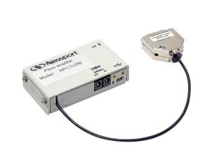 | NPC1USBPiezo Stack Amplifier, Single Channel, Low Cost | |||||
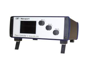 | NPC3Piezo Stack Amplifier, 3 Channel, Open-loop Position Control | |||||
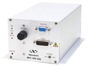 | NPC300DIGPiezo Stack Amplifier, Single Channel, 300 mA | |||||
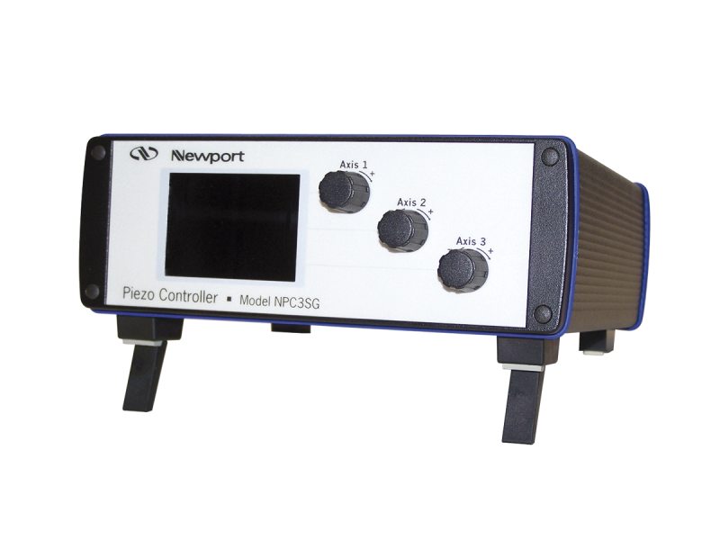
| NPC3SGPiezo Stack Amplifier, 3 Channel, Strain-Gauge Position Control | 4 Weeks |
Features
3-Channel Piezoelectric Amplifier
The NPC Piezo Stack Controller series allow for control of up to 3 axes. The models *DIG *SG are designed for NanoPositioning products with strain gauge position feedback. They support open-loop (voltage) control and closed loop (position) control. In both cases, the monitor output provides a voltage signal proportional to the actual position (0-10V). Since the open-loop response of a piezoelectric element is faster than the closed-loop response, it can be advantageous for certain applications to use open-loop voltage control while monitoring the position via the monitor output. The model NPC3 and NPC1USB operate in open-loop only and do not read feedback from strain gauges.
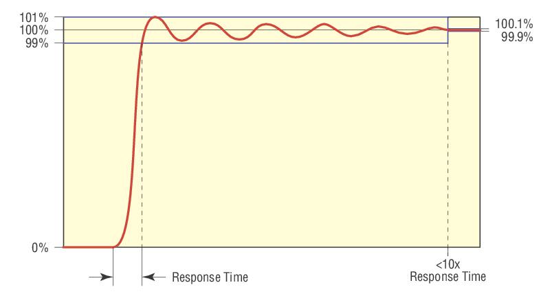
Dynamic Closed-loop Performance
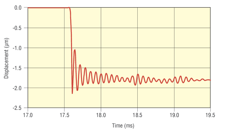
Dynamic Open-loop Operation
Open Loop Boundary Conditions
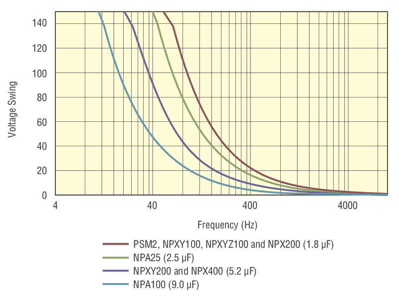
Another boundary for fast open-loop operation is the current that can be provided by the piezoelectric amplifier. The diagram displays the max. sinusoidal frequency which can be supplied by the NPC3 and NPC3SG amplifiers as a function of the capacitance of the piezoelectric transducer and the voltage amplitude. For other models please see user manual for drive frequency curves.
Sensor Pre-amplifier and SIC
Manual Control Mode
In manual control, the output voltage/position can be set for each channel separately using the 30 step encoder knob on the front panel (where applicable). Pressing the knob toggles between open-loop and closed-loop. The last setting is saved in memory and is loaded after restart.
Analog Control Mode
Computer Control Mode
Accessories
Compatible Stages
| Compare | Description | Drawings, CAD & Specs | Avail. | Price | ||
|---|---|---|---|---|---|---|
 | XPS-DRVP1Nano Positioning Drive Module, Piezo-Stack | In Stock FREE 2-day shipping on thousands of products on Newport.com Learn More | ||||
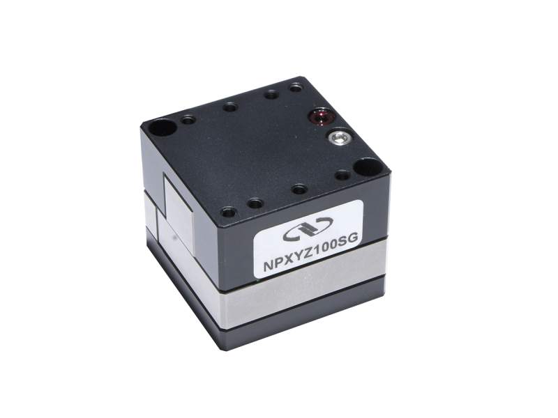 | NPXYZ100SGPiezo XYZ Linear Stage, 100 µm Nanopositioning, Strain-gauge | |||||
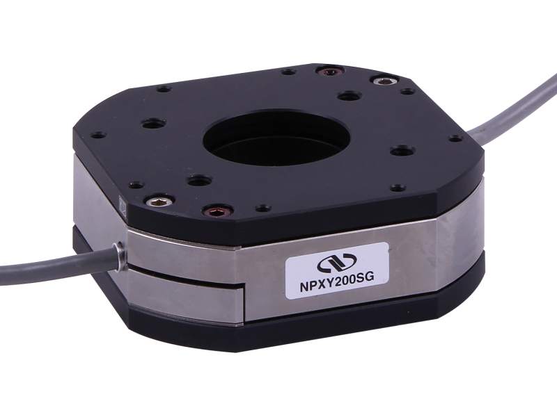 | NPXY200Piezo XY Linear Stage, Open-loop, 200 µm Nanopositioning | In Stock | ||||
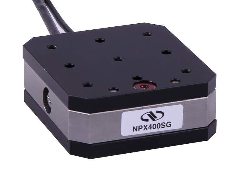 | NPX400Piezo Linear Stage, 400 µm Nano-Positioning, Open-loop | In Stock | ||||
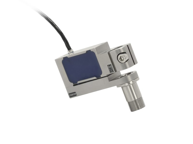
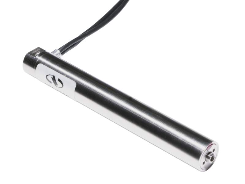 | NPA100Piezo Stack Actuator, 0.1 mm Travel Range, Open-loop | In Stock | ||||
 | NPM140Micrometer Adapter, Piezo-electric, Open-loop, 140 µm | 6 Weeks |

Resources
Manuals
old NPCxxxDIG Amplifier User's Manual(1.4 MB, PDF) NPC & NPCSG Series Amplifiers User's Manual(1 MB, PDF) NPC3 & NPC3SG Controllers User's Manual(2.5 MB, PDF)
Technical Notes
Tech Note - Piezo Theory-Physics and Design.pdf(559 kB, PDF) Tech Note - CH2 Piezo Theory-Static Properties.pdf(243.9 kB, PDF) Tech Note - CH3 Piezo Theory-Dynamic Properties.pdf(125.8 kB, PDF)
Software
USB Driver Installer(1.7 MB, ZIP) NPC3SG Labview V8.5(547.6 kB, ZIP) NewportUSB(357.9 kB, ZIP)
Literature
Nanopositioning Solutions(9.3 MB, PDF)