Laser Diode and LED Light Characteristics

Semiconductor lasers offer the benefits of efficiency, electrical pumping, and the ability to easily integrate with modern electronics which contribute to their ubiquitous usage. However, some of their output characteristics, particularly in terms of output power and beam quality, are considerably less than what can be achieved with other types of solid-state lasers. For instance, the small and asymmetric junction region from which radiation is emitted leads to a laser beam that does not possess an ideal TEM00 mode and is highly divergent, spreading unequally in two directions. The lasing bandwidth is large enough that multimode operation is likely and the spectral purity is not as good as most solid-state lasers. Furthermore, it can be difficult to achieve high output powers with single-mode operation due to the possibility of optical damage and thermal management issues. Numerous approaches have been developed to mitigate these issues, leading to more desirable output characteristics for laser diodes. These topics, along with the differences between laser diodes and LEDs, are discussed in this section.

Output Power

Due to the large number of semiconductor materials and device architectures, the range of output powers for LEDs and laser diodes can be quite large. However, estimates of typical output powers can be gauged based on the product of the device responsivity and the nominal operating current. For low-power devices, laser diodes typically operate with a few 10’s of mA to over 100 mA, whereas LEDs generally operate in the few mA to 20 mA range. For high-power devices, multimode laser diodes can operate with > 10 A, while high-power LEDs can easily exceed currents of 20 mA. The > values of Rd for a laser diode often fall in the range of 0.2 – 1 mW/mA (or W/A). An LED has a lower extraction efficiency than a laser diode; therefore an LED’s value of is necessarily smaller than that d. One final parameter that is often quoted for LEDs and laser diodes is the power-conversion efficiency (ηc) or wall-plug efficiency. ηc is the ratio of the emitted output power to the electrical input power. Laser diodes can readily exhibit values of .c that exceed 50%, which is significantly greater than most other types of lasers.
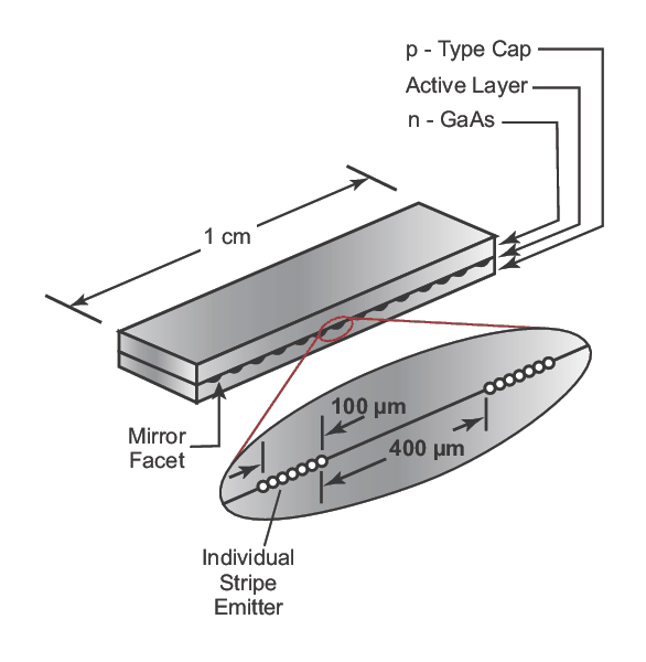
High-power laser diode bar consisting of serially repeated diode arrays
Figure 1. High-power laser diode bar consisting of serially repeated diode arrays.
There are many applications that require high laser output powers (> 10 W), including the optical pumping of solid-state lasers. The attributes of laser diodes make them intriguing candidates for such applications, but single devices cannot generate these types of powers. This limitation stems from the issues that arise when one tries to increase the gain per unit volume of a single device by increasing the width of the emission region and the injection current. Increasing the width leads to multiple transverse modes (see spatial profiles section below) which causes poor output beam quality, while large currents can lead to thermal loads in the active region that limit output power. Large output power densities at the cleaved facets can lead to optically-induced damage. One method to overcome these issues is to optically combine high-power single devices to achieve a high brightness output, which can be coupled into fibers for pumping DPSS or fiber lasers. A related method is to utilize an array of semiconductor laser diodes, which are fabricated adjacent to one another (see Figure 1). This method is feasible due to the large power-conversion efficiencies of the individual laser diodes. Depending on the spacing between the lasers, the combined output can either be coherent or incoherent with the latter generating larger output powers. These diode arrays can also be combined with one another to form two-dimensional arrays or a longer single array, typically referred to as a diode bar owing to its elongated rectangular structure (see Figure 1). These diode bars are ideal for DPSS lasers and can readily generate output powers in excess of 50 W.

Spatial Profiles

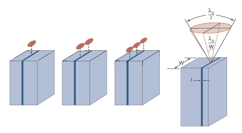
Spontaneous emission from an LED is isotropic but, when this radiation emanates from a planar surface, it is Lambertian. This means that the intensity decreases with the cosine of the angle from the plane-normal, effectively diminishing as one goes off-axis. As discussed in Laser Diode and LED Light Characteristics, the radial extent of the beam depends on the extraction cone. Describing the spatial profile of the beam emitted from laser diode is more complicated owing to the fact that the transverse modes are determined by the dielectric waveguide that makes up the active region of the diode. This junction region for an edge-emitting laser resembles a stripe whose width is much larger than the depth. The depth (l) is the region over which carrier recombination occurs and, by virtue of the DH architecture, is typically much smaller than the laser wavelength (λ0). This ensures that only a single mode will be emitted in the direction perpendicular to the junction plane. The width (w) of the active region is typically larger than λ0 and so multiple so-called lateral modes can exist in the direction parallel to the plane (see Figure 2). The width can be reduced to produce a single spatial mode using gain-guiding and index-guiding methods. Additional methods for ensuring single transverse mode output involve the use of an external cavity or appropriate anti-reflection coatings on the crystal facets.
Illustration of spatial distributions consisting of multiple transverse modes for an edge-emitting laser diode
Figure 2. Illustration of spatial distributions consisting of multiple transverse modes for an edge-emitting laser diode (left) and the angular distribution for a single transverse mode (right).
Even if a single transverse mode is achieved from the output of the laser diode, the divergence of this mode is significantly larger than nearly any other type of lasers. This divergence is the result of diffraction (since the cross-section of the active region is on the order of λ0) and a short cavity length, which prevents the high degree of collimation typically enjoyed by other laser systems. The angular divergence of the beam is proportional to the ratio of λ0 to the dimension of the active region (l). Given the small values of l, this can easily give rise to divergence angles exceeding 25° in the direction perpendicular to the junction (most solid-state lasers have angles much less than 1°). Since w is typically several times larger than l, the divergence in the direction parallel to the junction plane is significantly lower. This unequal divergence in orthogonal directions is called astigmatism and can make collimating such a beam quite difficult. However, optical systems have been developed to compensate for this astigmatic behavior.

Spectral Characteristics

The spectral distribution from an LED is centered at the transition wavelength (λg) associated with Eg (see Laser Diode and LED Physics). For a laser diode, the center wavelength (λ0) typically occurs at λg as well since the gain bandwidth follows the spontaneous emission distribution. However, if a frequency-selective approach is used to isolate a single longitudinal mode (see below), continuous tuning of λ0 under the gain bandwidth is possible. Finally, the carrier concentrations in the valence and conduction bands are dependent on the temperature of the semiconductor and the injection current. Since the carrier concentration plays a role in determining the effective value of Eg and therefore λg, the emission wavelength can be shifted with either drive current or junction temperature.
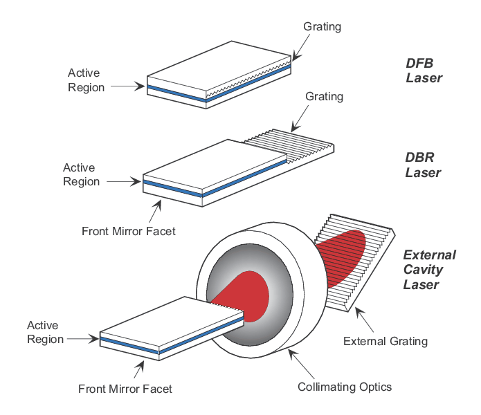
Frequency-selective feedback methods for generating single-longitudinal mode operation in a laser diode
Figure 3. Frequency-selective feedback methods for generating single-longitudinal mode operation in a laser diode.
The width of an LED’s spectral distribution is proportional to λg2, which leads to emission bandwidths in the VIS portion of the spectrum of ~10 nm while NIR emission bandwidths can approach 100 nm. As with other lasers, the spectral bandwidth of a laser diode depends on the overlap between the laser gain bandwidth and the laser cavity properties, which determine the longitudinal mode spacing. As expected for a solid-state medium, the gain bandwidth of a semiconductor laser is relatively large due to the band-to-band transitions. The bandwidths are typically a few THz (corresponding to ~10 nm in the NIR), which are larger than most lasers but still smaller than many solid-state systems. The cavities for most laser diodes are a few mm’s in length and so the longitudinal mode separation is 50-100 GHz. This is much greater than most other types of lasers and implies that far fewer longitudinal modes will lase under the gain bandwidth. Since frequency-selective techniques have few modes among which to discriminate, narrow-frequency output (< 10 MHz) is more readily achievable by forcing operation in a single longitudinal mode. The four main frequency-selective approaches for accomplishing this are coupled cavity, frequency-selective feedback, injection locking, and geometry control. The geometry control approach simply increases the longitudinal mode spacing such that only a single mode resides under the gain bandwidth. The coupled cavity approach amounts to using an intracavity etalon. Injection locking uses a narrow-frequency laser whose output will be preferentially amplified in the semiconductor gain medium over the spontaneous emission spectrum. Frequency-selective feedback is the most common method (see Figure 3). It involves either the use of a grating external to the laser or a internally-fabricated grating that makes use of DFB or DBR structures. DFB involves a periodic variation in either the gain or the index of refraction of the medium, which provides both the feedback and frequency-selection for the lasing process. DBR structures allow the periodic index structure to be present at the two cavity ends, and constructive interference occurs at a specific frequency.

MKS Semiconductor Handbook Cover

For additional insights into photonics topics like this, download our free MKS Instruments Handbook: Principles & Applications in Photonics Technologies

Request a Handbook