Advanced Bioimaging

Optical microscopes have been instrumental in the study of the life sciences for centuries. Since the invention of the laser, many advanced bioimaging techniques using microscopy have been created with progress accelerating greatly in the last two decades. Limitations in optical penetration depth, due to the scattering of light, originally limited studies to thin samples and, by necessity, processes taking place outside of the organism (ex vivo). In recent years, in vivo techniques have been developed that can visualize within the living organism or cell and have led to greatly increased understanding of cell function. Any bioimaging technique requires generating a signal from each portion of the cell or organism through some method of contrast. Some of these techniques require an exogenous contrast agent (originating outside of the organism or cell) to be added to the sample under investigation, such as a fluorescent dye. These agents can be specifically engineered and targeted to particular molecules. In other cases, the signal can be generated with endogenous contrast agents (those that originate naturally from within the organism or cell). This route has the advantage of not perturbing the original tissue micro-environment and limits possible cell toxicity.

Traditional microscopy techniques provide excellent spatial resolution, typically below 1 µm, in the lateral directions (within the plane of the sample). However, the axial resolution, into the depth of the sample, is typically much poorer. Multiple advanced bioimaging techniques have been developed to improve the axial resolution and allow a true 3D representation of the sample to be reconstructed. Chief among these techniques is confocal microscopy, where the axial resolution is improved by the addition of a confocal aperture that discriminates against light emanating from different depths in the sample. Confocal microscopy is described in Two-Photon Fluorescence Microscopy.

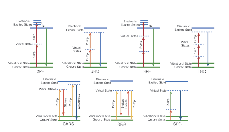
A wide range of laser-based nonlinear microscopies have been developed in the last two decades that make use of the high peak powers available from ps and fs laser sources. In each case, the excitation is due to an intensity-dependent effect which is most efficient at the focus of the laser beam. This can improve the axial resolution to about 1 µm without the use of a confocal aperture. Super-Resolution Microscopy, Two-Photon Fluorescence Microscopy, and Three-Photon Fluorescence Microscopy describe nonlinear microscopy techniques and a summary of the various mechanisms that enable these techniques is presented in Table 1. Laser Spectral Tunability describes various types of wavelength conversion and generation processes that are pertinent to these techniques. All of the techniques require a high peak power ultrafast laser and some require two synchronized ultrafast lasers at different wavelengths. Some techniques are applicable to endogenous contrast agents while others require the addition of a fluorescent dye. Figure 1 shows the energy level diagram for each mechanism which reveals how the laser light interacts with the system to produce a measurable signal. These diagrams will be referred to in the following sections.

Technology  Fluorescent Dye  Pulse Duration  Number of Synchronized Wavelengths 
Two-Photon Fluorescence (2PF)  X  fs 1
Second Harmonic Generation (SHG)  fs 1
Three-Photon Fluorescence (3PF)  X  fs 1
Third Harmonic Generation (THG)  fs 1
Coherent anti-Stokes Raman Scattering (CARS)  ps or fs 2
Stimulated Raman Scattering (SRS) ps or fs 2
Sum-Frequency Generation (SFG) fs 2

Table 1. Comparison of mechanisms used for nonlinear microscopy techniques.

Energy level diagrams for the mechanisms described in the above table
Figure 1. Energy level diagrams for the mechanisms described in the above table.

Two-Photon Fluorescence Microscopy

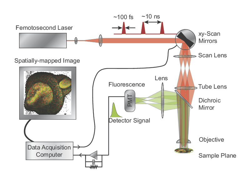
In a confocal laser scanning microscope, the fluorescence generated from a focused laser is imaged onto a pinhole, or confocal aperture, which blocks the fluorescence that is generated above or below the focal plane before reaching the detector. The intensity of the fluorescence is then measured as the beam is scanned horizontally across the sample to build up a 2D image. Finally, the sample is sequentially moved in the Z direction, allowing for 3D image construction with a spatial resolution close to the diffraction limit. This technique of confocal laser scanning microscopy dates back to 1969. A schematic of a two-photon fluorescence (2PF) microscope is shown in Figure 2. Please see Two-Photon Fluorescence Microscopy (2PF) for additional information.
Schematic of a two-photon fluorescence (2PF) microscope
Figure 2. Schematic of a two-photon fluorescence (2PF) microscope.

Three-Photon Fluorescence Microscopy

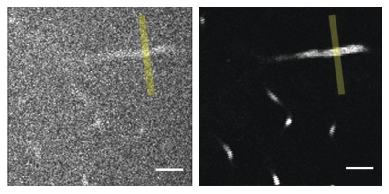
Three-photon fluorescence (3PF) microscopy can provide a significant advantage over 2PF microscopy in strongly scattering samples such as the mouse brain. The fluorescence from three-photon excitation falls off as 1/z4, where z is the distance away from the focal plane, while the fluorescence from two-photon excitation falls off as 1/z2. Thus, three-photon excitation reduces the background from regions away from the focal plane and improves the signal-to-background ratio by orders of magnitude. This reduction in background is illustrated in Figure 3 where 2PF and 3PF are compared. Please see Three-Photon Fluorescence Microscopy (3PF) for additional information.
A comparison of images from 2PF and 3PF microscopy of fluorescein-labeled blood vessels 650 µm deep in a mouse cerebellum
Figure 3. A comparison of images from 2PF (left, at 920 nm) and 3PF (right, at 1300 nm) microscopy of fluorescein-labeled blood vessels 650 µm deep in a mouse cerebellum. The two images have comparable signal strength and were displayed with the same contrast setting. Scale bar, 50 µm..

CARS and SRS Raman Microscopy

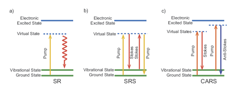
Raman microscopy is a technique that enables label-free chemical imaging. It is based on the Raman scattering effect of molecules that was discovered by C.V. Raman in the early 1930s. When light with a particular wavelength or photon energy is incident on a molecule, it can be inelastically scattered. This means that part of the energy is absorbed by the molecule and the scattered photon has a lower energy than the incident photon (see Figure 4). The fraction of the energy absorbed depends on the vibrational frequencies of the molecule. All molecules have specific Raman frequencies, typically given in wavenumbers, which span from 100 cm-1 to 3500 cm-1. A molecule's Raman spectrum is highly dependent on its chemical structure but mostly unaffected by the local environment. Therefore, Raman spectroscopy is not only specific but also robust to environmental variability. Please see Raman Spectroscopy (CARS and SRS) for additional information.
Energy diagrams of Raman interactions: Spontaneous Raman (SR), SRS, and CARS
Figure 4. Energy diagrams of Raman interactions: Spontaneous Raman (SR), SRS, and CARS.

MKS Semiconductor Handbook Cover

For additional insights into photonics topics like this, download our free MKS Instruments Handbook: Principles & Applications in Photonics Technologies

Request a Handbook