Stray Light in Monochromators and Spectrographs

The exit beam from a typical monochromator should be monochromatic but usually contains undesired light of other wavelengths. Filters can be used to block higher order diffracted wavelengths. Other unwanted light, called stray light, has several causes and should be minimized for both monochromators and spectrographs.

The amount of stray light measured on top of true signal will depend on many experimental factors as well as the performance of the instrument. When comparing stray light specifications, it is important to compare values that were measured under identical circumstances. The spectral distribution of the source and the response of the detection system are often the dominant factors when determining a stray light value.

Causes of Stray Light

Stray light may have a variety of origins. Its presence may be caused by a wide variety of design and manufacturing factors. The level of stray light due to the dispersed radiation inside a monochromator or spectrograph is affected by the design of the instrument, its baffles and interior finish.

Usually, part of this unwanted light, called re-entrant spectra, is due to diffracted light being directed onto the entrance, collimating or focusing mirror, and then back towards the grating. Light can also be reflected off a focal plane detector such as a diode array back into a spectrograph and similarly cause re-entrant spectra.

The output of most fiber optics, characterized by the fiber F/#, is too divergent for efficient acceptance by a monochromator or spectrograph. This leads to potentially significant loss in efficiency and increased stray light due to the overspill of the beam inside the instrument

Stray Light Considerations for Spectrographs

In a spectrograph / detector array system, stray light can be a more significant problem than it is with scanning monochromators. The array is a much larger target for stray radiation; there is no exit slit to limit the field of view for the detector. Some signal is reflected back off the array where it is scattered as stray light, and the array itself typically has less dynamic range than single element detectors.

It is difficult to characterize the stray light behavior of spectrographs. As with monochromators, variation in spectral content of your source, grating choice, and type of signal, contribute to stray light. The structure and choice of array, wavelength region, and internal specular reflections add to this changing picture for spectrographs.

All Oriel Spectrographs are designed for low stray light. The Oriel MS260i™, MS125 and MS257™ spectrographs conform to design rules that eliminate re-entrant spectra. Re-entrant spectra are due to diffracted radiation being reflected off the detector or one of the mirrors, back to the grating, where it is diffracted again and then focused onto the array. Without proper elimination of stray light, ghost spectral lines appear, disappear and move when the wavelength changes.

Designing a System to Minimize Stray Light

Oriel monochromators and spectrographs are designed to minimize stray light. The Ebert-Fastie out of plane design used in the model 77250 monochromator has no re-entrant spectra, and neither does the model 77781 MS257 monochromator. Re-entrant spectra are absorbed on baffles and by tilting the detector in the MS125 spectrograph.

The grating used and the operating wavelength are additional contributors to stray light. Oriel uses low stray light gratings mounted to black, low reflectance mounts. Stray light also depends strongly on such external factors as the intensity and spectral distribution of the input source and detector's spectral response.

To further minimize stray light, the following suggestions may be implemented:

  • Use an integrating sphere to uniformly illuminate the spectrograph or monochromator input.
  • If an integrating sphere is not used, place the light source at normal incidence to the instrument's input.
  • Match the f/# of the light source to the spectrograph or monochromator F/#.
  • If using fiber optics, utilize the Oriel 77529 F/# Matcher.
  • For a major improvement in the signal to stray light ratio, use a double MS257 monochromator.
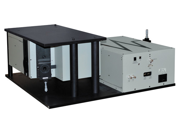
Two MS257 monochromators, model 77781 are mounted together in a double subtractive configuration
Figure 1. Two MS257 monochromators, model 77781, are mounted together in a double subtractive configuration.

F/# Matching Reduces Stray Light

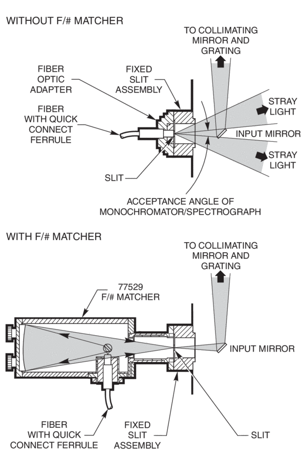
Fused silica fibers are approximately F/2, while Oriel's monochromators and spectrographs are close to F/4. To reduce stray light and increase throughput, the 77259 F/# matcher may be used at the input or output of the instrument. The F/# matcher may be used in imaging applications, but it must be noted that the image is magnified by a factor of 2x.

Glass bundles are F/1, so the use of the 77259 F/# matcher is not enough to match it to the F/# of the monochromator or spectrograph. However, it is still useful to utilize the F/# matcher with glass fiber optics because it may still decrease stray light and increase throughput, depending on the slit size.

When coupling a collimated beam of light directly into the monochromator or spectrograph, the light must be focused at the plane of the input slit. The focusing lens should be selected to match the F/# of the instrument and be placed at the correct distance from the input slit to achieve focus at the slit plane.

The 77529 F/# Matcher reduces stray light by matching the output angle of a fiber to the input angle of a spectrograph or monochromator
Figure 2. The 77529 F/# Matcher reduces stray light by matching the output angle of a fiber to the input angle of a spectrograph or monochromator.

Measuring the Stray Light of a Monochromator

When comparing stray light specifications, it is important to compare values that were measured under identical circumstances. Here are two stray light tests to provide some meaningful points of comparison. Both measurements used an Oriel UV-VIS photomultiplier tube, Model 77340. The first test also used one of Oriel's Series Q Deuterium Light Sources.

Measurement 1

Measurements were made with and without a glass plate in the beam. The glass blocks all radiation below 320 nm. Using a holographic grating blazed at 250 nm, the signal at 210 nm without the glass in place was 0.1% of the signal at 210 nm without the glass. At 250 nm, the stray light signal was only 3x10⁻⁴ of the unblocked signal.

This comparison is based on a taxing but real measurement scenario, measuring monochromatic UV light in the presence of a source producing scattered UV-VIS and a detector being able to sense both the UV and VIS light. The test is similar in principal to ASTM E387, Standard Test Method for Estimating Stray Radiant Power Ratio of Dispersive Spectrophotometers. The test first records the signal at 210 and 250 nm. Then the entire desired signal is blocked by insertion of a glass plate; what remains is scattering radiation.

Measurement 2

Using a Helium Neon Laser at 632.8 nm focused on the slit in an F/4 cone, the average of the stray radiation readings at 612.8 nm and 652.8 nm was 1.5x10⁻⁵ of the signal at 632.8 nm. A ruled diffraction grating with a line density of 1200 lines/mm, blazed at 500 nm was utilized. In this case, the response of the detector is irrelevant, as the only light detected is at 632.8 nm. This measurement is primarily an indicator of the grating quality.