Photonic Crystal Fiber Basics
The field of Photonic Crystal Fibers (PCF) was first explored in the latter half of 1990's and quickly evolved into a commercial technology. photonic crystal fibers are generally divided into two main categories: Index Guiding Fibers that have a solid core, and Photonic Bandgap Fibers that have periodic microstructured elements and a core of low index material (e.g. hollow core). They can provide characteristics that ordinary optical fiber cannot, such as: single-mode operation from the UV to IR with large mode-field diameters, exceptionally high nonlinearity, numerical aperture (NA) ranging from very low to about 0.9, and optimized dispersion properties. Applications of PCFs are found in a wide range of research fields like spectroscopy, metrology, biomedicine, imaging, telecommunication, industrial machining, and military.
Fabrication and Characteristics
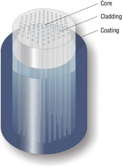
The typical starting point for manufacturing of an index guided PCF is an array of hollow capillary silica tubes bundled around a pure silica rod replacing the center capillary. For Photonic Bandgap (PBG) Fibers, one or more capillary tubes may simply be left out in the center of the preform in order to create a hollow 'defect' core. A sleeving tube surrounds the entire assembly that forms the preform. In a fiber draw tower, the preform is heated to around 2000°C and it is carefully pulled into fiber with the aid of gravity and pressure. Typical outer fiber diameter is 125 µm, but diameters from 80 to around 700 µm are routinely fabricated. This fiber maintains the structure of the preform, but now on a microscopic scale. Standard protective polymer coatings are applied to the fibers in order to improve handling characteristics.
The dispersion characteristics of PCFs can be manipulated to create fibers having zero, low, or anomalous dispersion at visible wavelengths. The dispersion can also be flattened. Combining these features with small mode field areas results in outstanding nonlinear fibers. By altering the pattern of air holes or the materials used, it is possible to manipulate other characteristics of PCFs, such as the single-mode cut-off wavelength, the NA, and the nonlinear coefficient. The design flexibility is very large, and designers can use many different, fascinating, and odd air hole patterns to achieve specific PCF parameters. The triangular arrangement of round air holes in the cladding is typically used to create single-mode fibers. Increasing the air-filling fraction in the cladding typically leads to multimode behavior. An elliptical core can create a highly birefringent fiber that is polarization maintaining.
Silica provides superior fiber performance for most applications with wavelengths between 200 and 2500 nm, but use of other materials can enhance specific parameters like nonlinearity or wave-guiding outside this spectral region. Furthermore, a long list of dopants can be added to silica. Doped silica is now used in a variety of fiber lasers and amplifiers; these could be combined with the unique capabilities of PCFs to provide even more useful devices. Coupling, splicing and connectorization of PCFs are other important issues because the fibers may have extreme parameters of mode field area and NA; coupling methods are in some cases very different from standard fiber methods. However, users may strip and cleave the PCFs with standard fiber tools. For laboratory use, the fibers are typically just cleaved and used with "open" ends. In such cases, it is important to avoid direct exposure of the fiber ends to any liquids since the capillary forces in the holes may draw the liquids several centimeters into the fiber, and thus disturb the wave-guiding properties.
PCFs can be spliced to standard fibers (and take advantage of the various connector schemes of such fibers), or the PCFs may be connectorized directly. Newport provides both PCFs spliced to standard fibers and directly connectorized on a semi-custom basis. Note that the mechanical strength of splices, the connectorized fiber core offset and connector-to-connector coupling are not always the same as standard fibers.
Directly connectorized fibers may furthermore provide beam expansion to lower the fiber end facet intensity and reduce the risk of damage at high power levels. Call Newport for more details.
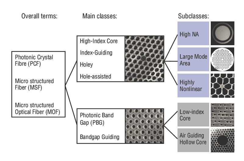
Index Guided Photonic Crystal Fibers
Newport's F-SM, and F-NL Series are index guided fibers. Similar to conventional fibers, index guiding PCFs transport light through a solid core by total internal reflection. The microstructured air-filled region in PCFs effectively lowers the index of the cladding – effectively creating a step-index optical fiber. The fiber behaves in many ways like standard step-index fibers, but it has a number of advantages. Index guiding PCFs are made of undoped silica that provides very low losses, sustains high powers and temperature levels, and may withstand nuclear radiation. Depending on PCF design, the air in the cladding may be utilized to yield fibers with extremely low or extremely high index steps.
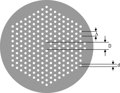
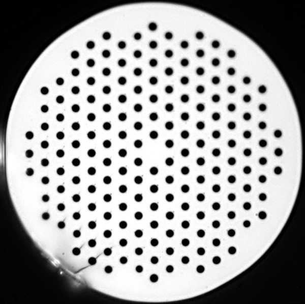
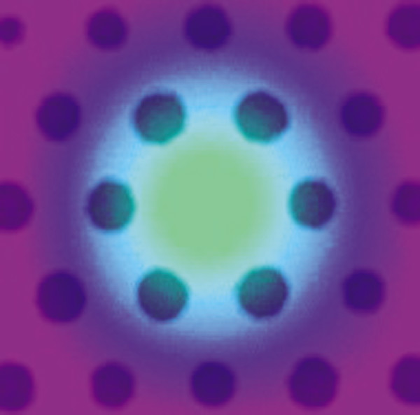
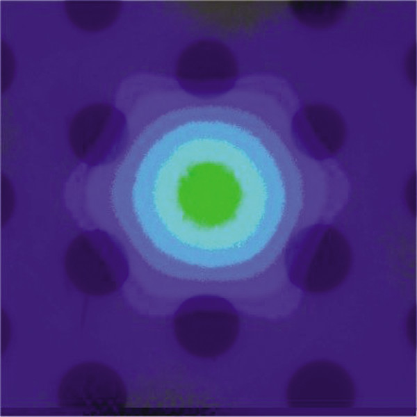
A typical cross section of an index guided PCF is shown in Figure 4. The PCF consists of a triangular lattice of air holes where the core is defined by a “missing” air hole. The pitch is labeled Λ, and measures the period of the hole structure (the distance between the centers of neighboring air holes). The hole size is labeled d, and measures the diameter of the holes.
Some PCFs have a cladding refractive index that exhibits a strong wavelength dependence. Together with the inherently large design flexibility, PCFs allow for a whole range of novel properties to be explored. Such properties include endlessly single-mode fibers (F-SM Series), extremely nonlinear fibers and fibers with anomalous dispersion in the visible wavelength region (F-NL Series). A unique feature of PCFs is that a single fiber may support single-mode operation over a wavelength range from around 300 nm to beyond 2000 nm – even for large mode field areas (of several hundred µm2). This allows PCFs to be utilized for transmission of very high powers with high beam quality without running into nonlinear or damage barriers (several hundred Watts for CW operation). On the other hand, the highly nonlinear fibers made as single-mode fibers have extremely small mode field areas (typically around 3 µm2) and confine light to the core region efficiently.
Compared to standard fiber technology, where the light is guided using solid glasses with different refractive indices, several new properties may be realized using PCF technology. For example:
- Fibers that are single-mode in a very broad spectral range (in principle all wavelengths)
- Very small mode sizes may be obtained (down to approx. 1 µm)
- Very large mode sizes may be obtained (up to 25 µm or larger)
- Zero dispersion wavelengths below 1300 nm is possible (down to approx. 600 nm)
- Exceptionally large birefringence close to 10-2 can be realized
- Very high numerical apertures up to 0.9 may be obtained
Hence, PCFs are ideally suited for applications requiring large non-linearities, broadband operation with single-mode guidance, large mode areas, light collection from a large solid angle, etc.
Hollow Core Photonic Bandgap Crystal Fibers
Extreme dispersion properties may be found in the photonic bandgap fibers, such as anomalous dispersion values in the thousands of ps/nm/km. Due to a negligible contribution from the core material (air), the total dispersion of PBG fibers is dominated by wave-guide dispersion.
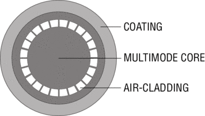
One very exciting feature of the PCF technology is the possibility of realizing fibers that guide light in a hollow (air) core, using the Photonic Bandgap (PBG) effect. The highly periodic structure of air holes in the cladding of the fiber creates a photonic bandgap. This means that light of frequencies within the PBG is not allowed to propagate out through the cladding and may be trapped in the core of the fiber. In contrast to index-guiding fibers, there is no requirement on the refractive index of the core region to be larger than the index of the cladding.
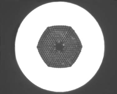
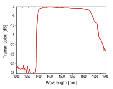
An inherent feature of PBG-Guiding is that the fiber only guides light in a limited spectral region. For fibers guiding around 1550nm, a typical bandwidth is ~200nm. Outside this region, the fiber core is anti-guiding. A typical transmission spectrum is shown.
Supercontinuum Generation with Photonic Crystal Fibers
Formation of broad continuous spectra through propagation of short femto or picosecond-range high power pulses through nonlinear media (also known as supercontinuum generation, or SCG) was first observed in 1970 and has since then been studied extensively in many different materials. The term supercontinuum does not cover a specific phenomenon but rather a plethora of nonlinear effects leading to considerable spectral broadening of optical pulses and thereby potentially octave-spanning output. The involved nonlinear effects depend on the dispersion in the material and count effects like self-phase modulation (SPM), Raman Scattering, phase matching and solitons.
Results on SCG in PCFs have previously been presented with pumping in the anomalous dispersion regime or at the zero-dispersion wavelength in both the visible and the infrared wavelength range. Most experiments utilize femtosecond pumping as this results in spectacularly broad spectra. Picosecond pumping yields more narrow spectra, but does so with far cheaper laser sources and is therefore commercially interesting.
Although SCG can be observed in a drop of water given enough pumping power, PCFs are ideal media for SCG as the dispersion can be designed to facilitate continuum generation in a specific region. In this way, it is possible to convert light to both higher and lower wavelength, just like super wide spectra covering more than an octave is achievable at previously unthinkable low power levels.
Practical Supercontinuum Tips
SCG-800 and SCG-800-CARS are ideal in generating supercontinuum using an ultrafast laser. When coupling light from a femtosecond laser into a crystal fiber, a number of issues regarding pulse distortion must be addressed to achieve the optimum performance. In this section, we discuss the precautions taken to couple light from a Ti:Sapphire Laser into a 1.7 µm core PCF. The first issue to be addressed is the 4% reflection from the fiber surface, which can lead to a distortion of the pulse train and in severe cases will stop the laser from mode-locking. Cleaving the fiber at an angle can minimize back reflections. However, we recommend that the problem be avoided by the use of a Faraday Isolator. Coupling out a small portion of the beam and directing it to Newport's PulseScout Autocorrelator allows for real-time monitoring of the pulse width and beam quality.
The femtosecond pulses are easily coupled into the fiber through standard microscope objectives. Magnifications of 40x and 60x provide good results. Aspheric ball lenses can also be used, but as these are not achromatic, they should not be used with short femtosecond pulses due to the broad spectral range of these pulses. The dispersion in the microscope objective should be compensated using a precompensating prism or grating compressor in order to launch the shortest possible (i.e. highest intensity) pulse into the fiber. The diameter of the laser beam should match the aperture of the microscope objective. This is easily achieved with a standard telescope.
Nonlinear effects are inherently very sensitive to variations in the input power, thus a very stable mount is needed. To avoid displacement of the fiber end due to thermal, acoustic and other unwanted effects, the fiber should be mounted as close to the end as possible. Gluing the fiber to the mount, or using a connectorized fiber, can create further stability.
If polarization-maintaining fibers are used, the polarization axis of the linearly polarized femtosecond pulses should coincide with one of the principal axes in the fiber. The relative orientation of the axes can be controlled either by a half-wave plate or by rotating the fiber. To find the principal axis one can measure the polarization state of the output and rotate the half-wave plate or the fiber until the output is linearly polarized. When using the above described alignment procedure, coupling efficiencies well above 40% are routinely achieved.
Available Photonic Crystal Fibers