Calculating Monochromator Throughput

What follows are two sample calculations of throughput. The purpose of these two examples is to help you estimate the available monochromatic power or monochromator throughput for a detection system. The two somewhat different examples can be adapted to many of our light sources or to luminescing samples.

The calculation of monochromator throughput may be summarized as follows

P0 = PiVFEmR4

Where:

P0 = Output power in mW

Pi = Power incident on the slit plane in mW

V = Vignetting factor due to the slit aperture being smaller than the source image

F = (F/#illumination)2/(F/#monochromator)2

(It reflects any mismatch in illumination F/# and monochromator F/#; F=1 for F/# Illumination≥F/# monochromator.)

Em = Grating efficiency

R = Reflection efficiency of one of the monochromator mirrors. The R4 factor implies 4 reflections.

Note that usually only Pi and Em have a significant variation with wavelength.

Other Factors

We have omitted some considerations to avoid further confusion. In some circumstances, these secondary considerations can be important. These include:

F/Number Matchers

These are used to increase the throughput into a monochromator and decrease stray light, but careful consideration must be made into how they are used. The Oriel 77259 F/Number Matcher, particularly for use with fibers, has a throughput of about 75%, and increases the F/Number of the illuminating beam by a factor of two over that directly from the fiber. The F/Number Matcher also increases each apparent linear dimension of the illuminating source by a factor of two. Since this may increase vignetting by the monochromator slit, the final throughput may or may not be increased.

Source Intensity Distribution

The analysis is greatly simplified by assuming uniform rectangular Lambertian sources. Real sources do not conform to this ideal. The high intensity regions of arc sources can sometimes be exploited to your advantage.

Lens Losses

Fresnel reflections from the lens surfaces cost power. Use anti-reflection coated lenses in critical situations.

Lens aberrations preclude exact imaging. This is a significant problem with small sources and low F/# lenses that produce a blur circle larger than the expected source image.

Monochromator Anamorphism

The grating in the monochromator is tilted for proper dispersion. This means that the acceptance pyramid is actually a wavelength dependent rectangle, and the entrance slit image at the output is narrower or wider than the entrance slit, depending on grating tilt direction. This can be important for high angles of grating tilt, and in these cases different slit factor widths are needed for best performance. Our variable slits allow you to optimize slit widths easily.

Marginal Ray Loss

A simple optical sketch shows that rays entering a slit within the acceptance cone of the monochromator but at the top and bottom of the slit, can miss the collection optics. A field lens at the entrance slit can reduce this loss (and a field lens at the exit slit can improve optical detection.) We find no advantage to this solution for most of the monochromatic sources based on small intense arcs or filaments.

Polarization

Diffraction gratings exhibit complex polarization effects. The grating is more efficient for either s or p polarization. This has no affect on power throughput for an unpolarized input but the monochromatic beam which emerges will be partially polarized and the degree of polarization is wavelength dependent. These phenomena can also cause misleading artifacts in radiometry and spectral analysis.

Example 1

Estimate the power out of the 77700 MS257™ as a monochromator at 450 nm using the 150 watt xenon arc lamp, 0.6 mm slits, 66919 Source and the 77742 Grating. The 66919 Source has an F/0.85 condenser. The beam from the condenser is focused on the input with a 127 mm focal length lens filling the monochromator input.

The first step is to estimate how much power reaches the slit plane. The source and lamp housing pages lists Lens Multiplication Factors which allow you to estimate the power from the source at any wavelength:

At 450 nm the irradiance from the 150 watt xenon lamp is 14.5 mW m-2 nm-1 at 50 cm and the Lens Conversion Factor is 0.13.

Therefore, the beam from the first lens has ~1.9 mW nm-1 at 450 nm.

Since the source has a rear reflector which contributes about 60% more radiation, we estimate the beam power as 3 mW nm-1. Note too, the secondary focusing lens transmission is about 0.9.

The arc size is 0.5 mm by 2.2 mm. It is important to note that this arc dimension produces only 60% of the total radiation. The outer regions of the arc produce the other 40%. All regions contribute to the 3 mW figure. Because of this, we base the calculation on a source of 0.5 mm by 2.2, providing 1.8 mW nm-1.

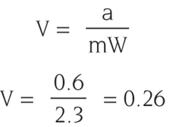
Following the pattern from the example on the previous page, the optics produce a 3.9/0.85 = 4.6 magnified image of the source on the slit. The source image size is then 2.3 x 10.1 mm, so with the assumption of a uniform image irradiance, the fraction of image power which passes through the slit is found using the vignetting factor (V). Again, since the image of the source is wider, but not taller, than the slit:

We can now estimate how much power nm-1 at 450 nm enters the monochromator:

1.8 mW nm-1 x 0.9 x 0.26 ~ 0.42 mW nm-1

The 0.6 mm slit corresponds to a bandwidth of 2.02 nm, so the power into the monochromator in this bandwidth at 450 nm is:

0.42 x 2.02 ~ 0.85 mW

How Much Comes Out?

The grating efficiency relative to aluminum is 0.7, so the actual efficiency is about

0.7 x 0.88 = 0.62.

In the lateral configuration the light is reflected off 4 aluminized mirrors inside the monochromator. Each mirror has a reflectance of about 0.88 at 450 nm so the output should be:

0.85 mW x 0.62 x 0.884 ~ 0.32 mW

The measured value is 0.24 mW, providing an excellent agreement, given the number of simplifying assumptions.

Example 2

Estimate the power in a 10 nm bandwidth at 500 nm when using the 77250 1/8 m Monochromator and operating a model 6332 50 W QTH lamp in the 7340 Monochromator Illuminator.

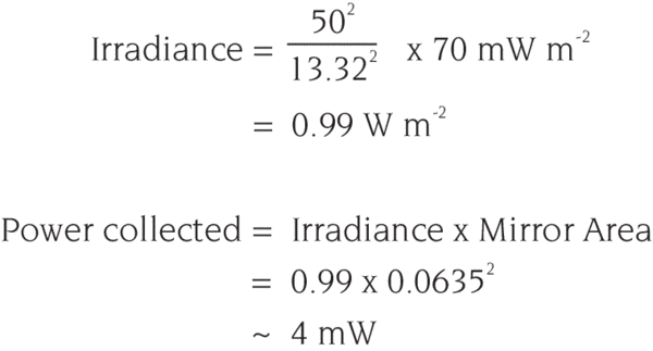
The 77298 Grating blazed at 350 nm gives best performance. The slits for 10 nm bandwidth are 1.56 mm wide. The first step is to estimate the amount of light collected by the mirror in the 7340. From the curves Information on Spectral Irradiance Data the irradiance at 50 cm from the bare lamp is 7 mW m-2 nm-1.

The power density in a 10 nm bandwidth is 70 mW m-2 . The mirror in the illuminator is 6.35 x 6.35 cm and 13.3 cm from the source. You can approximate the collected power using the inverse square law.

Power Through the Entrance Slit

The collected power is mostly reflected onto the monochromator slit plane. Reflection is approximately 88% efficient. Since the slit plane is 24 cm from the mirror the ratio of the source image to source size is

24/13.3 = 1.8

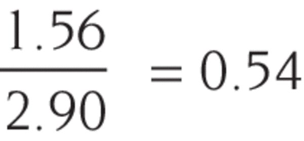
The source is 1.6 mm x 3.3 mm, therefore, the image size is 2.9 mm x 5.9 mm. The slit size is 1.56 x 12 mm. Assuming a uniform image makes calculating the fraction passing through the slit a simple geometrical calculation:

This factor, (1.56/2.90), is from the vignetting factor as in Example 1. The power through the slit is then:

0.88 x 0.54 x 4 mW = 1.9 mW

Power Through the Monochromator

The 7340 mirror overfills the grating of the monochromator. For a square grating of 30 mm size, a monochromator focal length of 125 mm, and the mirror dimensions above, a geometrical calculation indicates that 82% of the light strikes the grating. The grating efficiency is about 0.6 at 500 nm, and the reflectance of each of the four mirror surfaces is about 0.88 leading to a total transmittance of:

0.82 x 0.65 x 0.884 = 0.32

The calculated power output is 0.32 x 1.9 mW = 0.61 mW. The measured value is 0.5 mW. The difference is due in part to approximations made throughout. This power diverges from the monochromator as a pyramid with half angles of 6.8°.