Radiometric Measurement

Radiometry is the measurement of energy or power in electromagnetic radiation fields or light. The average output power is the most common radiometric measurement since many light sources, including CW lasers and LEDs, emit output power that is constant over time. For a pulsed source, the pulse energy is typically the radiometric unit of measure, although the average output power can be given as well. Since sources can have different spatial distributions and divergences, other parameters may be needed to fully characterize their outputs. For this reason, this section will discuss the most commonly-encountered radiometric quantities for measuring power and energy (see Table 1). There can be considerable confusion regarding the nomenclature of radiometric terms, which can lead to measurement errors if not properly understood. The discussion below aims to adhere to the International Commission on Illumination (CIE) system, which fits well with the SI system of units. For a more complete description of radiometry, its history, and its concepts.

Quantity  Usual Symbol  Typical Units 
 Power  φ  W
 Energy  Qe  J
 Irradiance  E  W / m2
 Fluence  F  J / m2
 Radiant Intensity  Ir  W / sr
 Radiance  Lr  W / sr x m2

Table 1. Commonly used radiometric quantities.

The parameters in Table 1 are defined as follows:

  • The average output power is defined as φ for a source with a continuous and stable output. For simplicity, φ is denoted as the power and is the radiometric quantity quoted most often.
  • For a pulsed source, φ becomes a time-dependent quantity, i.e., φ(t), with a peak amplitude and a temporal shape (see Pulse Characterization). This amplitude is referred to as the peak output power or peak power. This pulsed quantity should not be confused with the average output power.
  • The quantity Qe is the energy within a pulse of light. This quantity can be measured provided the temporal response of the sensor is fast enough; otherwise, it can be determined based on . and the repetition rate of the source.
  • The irradiance (E) is essentially the power per unit area or power density. The terms exitance and intensity are often used synonymously with E since they have similar meanings and identical units of measure.
  • The fluence (F) is associated with pulsed sources since it is the energy per unit area or energy density.
  • The radiant intensity (Ir) and radiance (Lr) are derivatives of power and irradiance that also account for the divergence or spreading of the light source based on radiation into a solid angle. Lr is also important when determining light throughput in an optical system.
  • If the word “spectral” is used before any radiometric quantity, it implies consideration of the wavelength dependence of the quantity. The measurement wavelength should be given when a spectral radiometric value is quoted.

In order to ensure that a sensor or detector (the two terms will be used interchangeably in this section) can accurately measure a radiometric quantity such as power or energy, it needs to be calibrated using a detection calibration standard provided by one of the national standards laboratories such as National Institute of Standards and Technology (NIST) or Physikalisch-Technische Bundesanstalt (PTB). Typically, the output of a source such as a spectrally-filtered lamp or a laser is measured by a NIST/PTB traceable sensor and this calibration is transferred to a master sensor which is, in turn, used to calibrate the sensor under test. Errors associated with each of these steps, along with any additional errors associated with spectral or temperature corrections, are combined to determine the total error associated with the calibrated sensor. The sensors should be periodically calibrated to ensure these errors remain reliable. Such absolute errors are related to the sensor’s ability to accurately measure the power or energy. This should not be confused with relative errors, which are related to the sensor’s precision. These errors are based on the noise characteristics of the detector.

All sensors that measure either power or energy from a laser or LED are typically described by a set of detector performance parameters. These parameters can be used as selection criteria when choosing the appropriate photodetector to characterize the source at hand. The three different types of sensors described in the following section each possess their own unique set of characteristics. These mainly result from the differences in their light-to-electrical signal conversion processes and are typically divided into thermal detectors (thermopile, pyroelectric) or photon detectors (photodiode). These detector performance parameters and how they differ for each type of sensor are the subjects of this section.

Spectral Responsivity

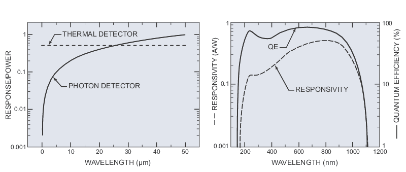
Responsivity is a measure of the transfer function between the input optical power and the output electrical signal from the detector. Thermal detectors convert a temperature change into a voltage; therefore, their responsivity is typically given in units of V/W. Photodiodes convert absorbed photons in a semiconductor into a current; therefore, the responsivity is given in A/W. Spectral responsivity describes how the detector will respond as a function of wavelength or photon energy. This spectral response can be dependent on a material’s transmission properties, e.g., a window in front of a sensor, or a material’s absorptive properties, e.g., a coating on a sensor or the sensor material itself. Thermal detectors respond to heat and so one watt delivered by a UV photon produces the same response as one watt delivered by an IR photon. Provided the material that is being heated has uniform absorption, the spectral responsivity is flat. The response for an ideal thermal detector is shown in Figure 1. Photon detectors produce at most a single response element, i.e., an electron-hole pair per incoming photon. The energy carried by individual photons is inversely proportional to the wavelength, and so, for the same input power, there are fewer UV photons per watt compared to IR photons. Accordingly, photon detector responsivity is significantly lower in the UV than in the IR (see Figure 1 for ideal response). Furthermore, due to the presence of the bandgap in semiconductors, only photons with energies above the bandgap energy (Eg) will be absorbed. Therefore, a photodiode will exhibit an abrupt increase in the responsivity for wavelengths just below the value associated with the bandgap (λg) while going to even shorter wavelengths will result in a decrease in responsivity like that described above. Figure 1 provides a representative spectral responsivity for a Si photodiode while actual responsivity curves for various photodiodes are given Photodiode Sensor Physics. Due to the strong wavelength-dependence of the responsivity for photodiodes, it is not uncommon for specification sheets to give a peak responsivity value at a wavelength and provide a relative spectral response curve.

Si photodiode responsivity and quantum efficiency (QE) where the QE is the probability that a single photon will generate an electron-hole pair that contributes to the current.
Figure 1. Relative spectral responsivities of perfect detectors (left). Si photodiode responsivity and quantum efficiency (QE) where the QE is the probability that a single photon will generate an electron-hole pair that contributes to the current (right).

Noise, Noise Equivalent Power, and Normalized Detectivity

A photodetector generates an output voltage or electric current that is proportional to the incident optical power. This output value generated by the device is a quantity whose value fluctuates above and below its average value. These fluctuations are generally regarded as noise and are typically quantified by the standard deviation of the value about its mean. There are numerous sources of noise in detectors, which are dependent on the type of sensor. Sources of noise can generally be grouped into photon noise, detector noise, and circuit noise. Photon noise is due to the discrete nature of radiation, which is composed of photons arriving randomly in time. In photodiodes, absorbed photons produce charge carriers at random intervals giving rise to a variation in current that appears as noise. Detector noise can result from temperature fluctuations in thermal detectors or the random recombination of charge carriers in photodiodes. Fluctuations in a detector’s internal resistance or in any resistance in series with the detector’s terminals can give rise to circuit noise.

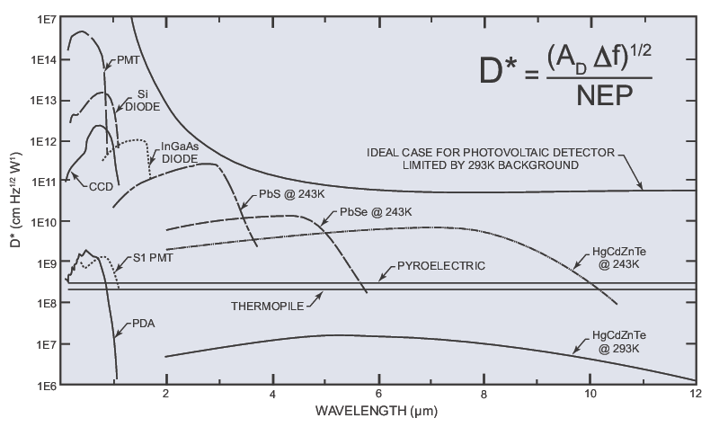
All sources of noise affect detector parameters such as the signal-to-noise ratio (SNR), the minimum detectable signal, and the detector sensitivity. The noise equivalent power (NEP) is the input power necessary to give an output signal that gives a SNR equal to one. Therefore, NEP is a measure of the minimum detectable signal for a sensor. NEP values are typically given in units of W/Hz1/2 and must be stated at a specified wavelength, modulation frequency, detector area, temperature and detector bandwidth due to its dependencies on these parameters. Detectivity is the reciprocal of NEP and therefore gives a more intuitive figure-of-merit that is larger for more sensitive detectors. For most detectors, electrical noise power is proportional to the area of the detector (AD) and its electrical bandwidth (Δf). Therefore, to compare different types of detectors independent of AD and Δf, the normalized detectivity (D*, pronounced “D-star”) is typically used. Figure 2 shows the formula for D* along with its spectral response for several common photodetectors. Two trends are immediately evident. Much like responsivity, D* is essentially constant across the entire wavelength range for thermal detectors while photodiodes show a strong wavelength dependence that is localized in a particular spectral region. However, photodiodes possess a much larger detectivity than their thermal counterparts.

Approximate D* values as a function of wavelength for various sensor types (PMT, CCD, PDA).
Figure 2. Approximate D* values as a function of wavelength for various sensor types (PMT – photomultiplier tube, CCD – charge-coupled device, PDA – photodiode array).

Linearity and Dynamic Range

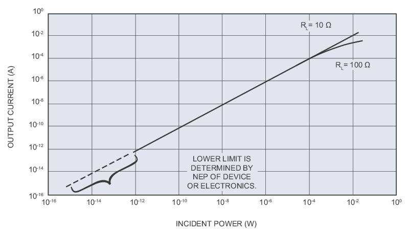
In order to be practically useful, a detector’s output should be linearly proportional to the input optical power. This linearity is typically defined for a range of input powers or energies based on when the response deviates from this linear response by a certain pre-determined amount (see Figure 3). This is called the dynamic range of a detector and essentially describes its usable range. The lower limit of the dynamic range is typically determined by the NEP or detectivity while the upper range may be device or external circuit limited. Photodiodes have very large dynamic ranges that can exceed 109 for properly designed circuits (see Figure 3 for example). Energy sensors, such as pyroelectrics and some photodiodes, often possess a reduced dynamic range compared to power sensors. To accurately measure the pulse energy, a detector must respond more rapidly (see temporal response below). Since detector response speed is often inversely proportional to detector sensitivity, the dynamic range is limited at lower energies by reduced detectivity, while recombination can limit the range on the high end for photodiodes.
Linearity of a Si photodiode showing the dynamic range of the detector.
Figure 3. Linearity of a Si photodiode showing the dynamic range of the detector.

Temporal Response

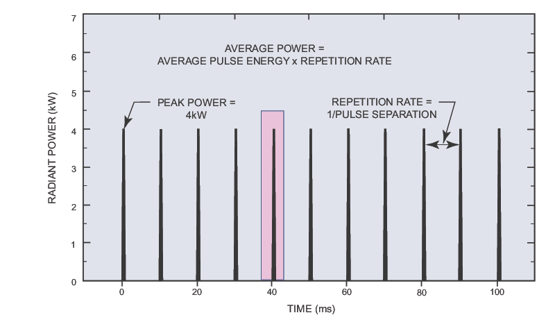
A pulsed source of light exhibits an output power, which is a time-dependent quantity, i.e., φ(t). Pulsed lasers possess a temporal shape and amplitude (see Section II.E) that is repeated in a pulsetrain with a certain repetition rate (see Figure 4). For an energy sensor to directly measure the pulse energy (Qe), it needs to be able to discriminate between pulses at this repetition rate. This can be seen in the following equation where φ(t) is integrated over a time interval (Δt) that encompasses an entire pulse:
Pulse energy equation- Qe
Equation 1. Pulse Energy
Clearly the temporal response of the detector must be fast enough to initiate this time interval and decay rapidly enough to eliminate contributions from the following pulse (see Figure 4). Such rise and fall time constants are frequently different, since different physical parameters may cause them. These topics are covered in Photoreceiver Characteristics where the more stringent requirements of fast photoreceivers are introduced. For an energy sensor, if the response time is sufficient to provide the required Δt, the pulse energy can be measured directly. Power sensors typically do not possess sufficient temporal response to measure the pulse energy directly, i.e., Δt is much longer than the time between pulses. In this case, the pulse energy can be estimated by dividing the measured average power by the repetition rate in Hz as detailed in Figure 4. In this case, one must assume an average pulse energy within the measurement period. As discussed above, there is an inherent tradeoff between speed and sensitivity that results in differences in dynamic ranges between power and energy sensors.
ypical laser pulsetrain, which indicates the time interval Dt of an energy sensor capable of directly measuring pulse energy.
Figure 4. Typical laser pulsetrain, which indicates the time interval Δt (red rectangle) of an energy sensor capable of directly measuring pulse energy. A power sensor, which measures the average power, estimates the average pulse energy based on the repetition rate.

Aperture

The irradiance (E) is the power per unit area or power density. The irradiance emanating from any laser or LED has a certain spatial distribution (details are given in Laser Beam Profile Measurement and Laser Light Characteristics, respectively, for each light source) which can be denoted as E(s). The active area of a detector (AD) has a finite size that is typically dictated by its aperture. Therefore, the size of the E(s) with respect to AD can affect the measured power or energy. The following equation quantifies this by showing the spatial integration of E(s) over the detector area:
Pulse energy equation- Qe
Equation 2. Spatial integration of E(s) over the detector area.
This results in a measured power or energy (the latter assumes a pulsed source such that the irradiance is also time-dependent). If the spatial extent of E(s) is larger than AD, e.g., an expanded laser beam and a small detector, only a fraction of the power or energy will be measured. Conversely, if E(s) is accommodated within AD, the total power or energy will be measured; therefore, proper care must be taken to ensure that E(s) is properly delivered to the sensor. For collimated sources, such as lasers, this typically amounts to using the proper focusing geometry such that the beam is significantly smaller than AD upon arrival. For highly divergent systems like laser diodes or for LEDs with omnidirectional output (see Laser Light Characteristics), more sophisticated collection geometries must be used to ensure the total power or energy is measured.

Damage

As detailed in Essentials of Laser Safety, the large irradiances associated with laser output can lead to optical damage, particularly to the surfaces of power and energy sensors. When laser beams are focused into these detectors to ensure proper collection, the probability of damage increases. For power sensors, specification sheets often include a maximum recommended irradiance or power density that lies below the LIDT of the detector to ensure compliance. These values are typically in the 5-50 W/cm2 range for pyroelectrics and photodiodes whereas they can be several orders-of-magnitude larger for thermopiles (see Laser Light Characteristics for examples). For energy sensors that measure pulsed lasers, the maximum values are typically given as an energy density or fluence (F). The fluence is essentially the temporally-integrated irradiance as shown below (the spatial dependence of E has been ignored):
Pulse energy equation- Qe
Equation 3. Energy Density or Fluence (F).

Types of Optical Sensors

The sensors discussed in this section are differentiated by the way in which they convert the incident light into an electrical signal. Thermal detectors work by converting the incident radiation into an increase in temperature. The temperature change is measured either by a voltage generated at the junction of dissimilar metals or by the pyroelectric effect. In either case, the heat-sensitive element is coated with a black material to enhance the absorption of the radiation. The material is designed to possess a large and uniform absorption leading to good responsivity over a wide spectral range. This is the major advantage of thermal detectors. As a result of the time required to effect a temperature change, thermal detectors are generally slow. In a photodiode, photons are absorbed in a semiconductor p-n junction giving rise to mobile charge carriers. The electrical conductivity of the material increases in proportion to the incident optical power. Applying an electric field to the junction causes the carriers to be transported, resulting in a measurable electric current in the circuit. The detectivity of photodiodes is typically much larger than that of their thermal counterparts and the mechanism for conversion can be quite fast. The main disadvantage of photodiodes is that their responsivity is strongly dependent on the wavelength of the incident light. Table 2 lists the typical characteristics of the three different sensor types.

Thermopiles  Pyroelectrics  Photodiodes 
 Measure power from mW up to 30 kW  Measure energy from sub µJ up to 40 J  Measure power from fW up to 30 W
Response times of 1-3 seconds Measure pulse widths up to 20 ms and repetition rates up to 25 kHz Inexpensive and compact
Linearity of ±1% Duty cycle - pulse width up to 25% of time between pulses Linearity of ±0.5% below saturation
Relatively independent of beam size and position on detector Accommodate beam sizes up to 96 mm diameter Large dynamic range Ñ over 9 orders of magnitude in one sensor
Broadband spectral response Broadband spectral response Large wavelength sensitivity Ñ must specify exact wavelength
High laser damage threshold Can measure low level CW powers with chopper Can measure sub µJ energies with reduced dynamic range

Table 2. Typical characteristics of various sensor types.


MKS Semiconductor Handbook Cover

For additional insights into photonics topics like this, download our free MKS Instruments Handbook: Principles & Applications in Photonics Technologies

Request a Handbook