Introduction to Polarizers
A polarizer is an optical component that is designed to filter, modify or analyze the polarization states of light. Polarizers can be integrated into optical systems to increase contrast, decrease glare or to measure changes in temperature, magnetic fields or gauge chemical reactions.
Polarization States
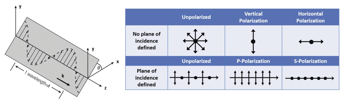
Since light is an electromagnetic wave, its wave has an electric field, and this wave oscillates perpendicular to the direction of propagation. Unpolarized light has the direction of this electric field fluctuating randomly in time. Examples of unpolarized light include the sun’s light, halogen lights, LED spotlights and incandescent lightbulbs. Polarized light’s electric field has a well-defined direction. Laser light is the most familiar example of polarized light. There are three kinds of polarizations, depending on how the electric field is oriented:
Linear Polarization
Linear polarization is when the light’s electric field is confined to a single plane along the propagation direction.
Defined relative to the plane of incidence of the light ray on a surface, there are two orthogonal linear polarization states that are important for reflection and transmission, p- and s-polarization. P-polarized light (from the German word parallel) has its electric field polarized parallel to the plane of incidence. S-polarized light (from the German word senkrecht) is perpendicular to the plane of incidence.
Circular Polarization
Circular polarization is when the electric field of light is made up of two linear components perpendicular to one another, of the same amplitude, but with a phase difference of π/2. The electric field that results will rotate in a circle about the propagation direction and, depending on the rotation direction, is referred to as right- or left-hand circularly polarized light.
Elliptical Polarization
Elliptical polarization is when light’s electric field describes an ellipse. This is caused by a combination of two linear components with different amplitudes or a phase difference that isn’t π/2. Elliptical polarization is the most common description of polarized light, while circular and linear polarized light can be looked at versions of elliptically polarized light.
Polarizer Definitions
Polarizer performance is commonly characterized by the following specifications:
k1: Principal transmittance or insertion loss is the transmission of linearly polarized incident light with the polarizer oriented for maximum transmission.
k2: Minor transmittance or blocking efficiency is the transmission of linearly polarized light with the polarizer oriented for minimum transmission.
Other performance characteristics that can be derived from the k1 and k2 values or directly measured are:
k1/k2: Principal transmittance ratio or contrast.
TT: Total transmittance, is the transmission of a single polarizer in unpolarized incident light = (k1 + k2) / 2
H0: Open transmittance, (k12 + k22) / 2, is the transmittance of two polarizers oriented for maximum transmission in unpolarized incident light.
H90: Closed transmittance, k1k2, is the transmittance of two polarizers oriented for minimum transmission in unpolarized incident light.
Degree of Polarization and Extinction Ratio
Linear polarizers exhibit polarizing properties that are usually defined by a degree of polarization efficiency (P) and its extinction ratio (ρp), which can vary with wavelength and incident angle.
P = (k1 - k2) / (k1 + k2) ρp = k1 / k2
Acceptance Angle
Acceptance angle is the maximum deviation from the design incidence angle where the polarizer will still perform within its specifications. Angles of incidence of 0° or 45° or at Brewster’s angle is where most polarizers are optimally designed to work.
Damage threshold
The material that is used in the manufacture of a polarizer and the actual polarizer design combine to determine the laser damage threshold. Birefringent polarizers have the highest laser damage threshold. Beamsplitters, which are two optics cemented together, will have low laser induced damage threshold and air-spaced birefringent polarizers have high laser induced damage threshold.
Dichroic Polarizers
The mechanism of polarization in a dichroic polarizer is selective absorption and transmission of incident radiation. Dichroic is the selective polarization absorption of the anistotropic polarizating material, also called diattenuation. Anisotropic means that a material exhibits the physical property that it has a different value when it is measured in different directions. Examples include oriented polymer molecules and stretched nanoparticles. Dichroic polarizers exhibit limited damage thresholds and environmental stability, with glass dichroic polarizers performing better than plastic dichroic polarizers in these areas. Dichroic polarizers are useful when very large apertures are needed for an application. They are also used for microscopy, imaging and display applications.
Polymer Polarizers
Precision linear polarizers are constructed by laminating a thin, stretched and dyed polymer polarizing film between two high-precision AR coated glass or fused silica windows. The polymer has been stretched and stressed in one direction to align the long polymer molecules to create a filtering effect, which allows light waves oscillating parallel to the direction of the stress to pass through, while blocking their polarization. The compact component that results is ideal for flux densities below 1 W/cm2. Polymer polarizers are used throughout the visible spectrum.
Thin Film Polarizers
Superior high-energy polarizer performance is achieved through advanced coating design and meticulous production procedures. These optics have been developed for use in some of the most demanding lasers in the world. Some polarizer coatings have been optimized for use with Nd:YAG lasers. When these polarizers are mounted at Brewster’s angle, extinction ratios exceed 100:1. Thin film polarizers have also been optimized for ultrashort pulses. These thin film polarizers have been designed to provide superior performance in ultrafast Ti: Sapphire regenerative amplifiers. While pulse lengths are relatively long in these amplifiers, pulse dispersion is still a concern if pulse width is to be maintained in the recompressed pulse. Multiple round trips in the amplifier have a multiplying effect on the dispersive characteristics of any optic in the cavity. For this reason, substantial effort has been made in designing and testing these polarizers for minimum pulse dispersion.
Calcite Crystalline Linear Polarizers
Calcite linear polarizers use birefringence in crystalline materials to modify the polarization of incident light. The transmission of the desired polarization and the deviation of the remaining light is directly related to birefringent materials’ index of refraction, as well as the angles of the cut between the crystals. Crystalline polarizers usually are made up of two birefringent crystals cut and aligned at specific crystalline axes in order to attain a particular polarization behavior outcome. Crystalline polarizers offer a high optical purity, which is ideally suited for a wide variety of laser applications that require high damage thresholds with optimized extinction ratios. These polarizers feature high extinction ratios up to 100,000:1 and are contained in a mountable anodized aluminum housing. The polarizers include Glan-Laser Calcite Polarizers, Glan-Thompson Calcite Polarizers, Rotatable Glan-Thompson Calcite Polarizers and Wollaston Calcite Polarizing Prisms.
Polarizing Cube Beamsplitters
Polarizing Cube Beamsplitters consist of a pair of precision right-angle prisms carefully optically contacted or cemented together to minimize wavefront distortion. A dielectric coating is placed onto the hypotenuse of one of the prisms. Polarizing beamsplitters are designed to split the light into two –reflected S-polarized and transmitted P-polarized beams. They can be used to split unpolarized light at a ratio of 50/50, as well as for polarization separation applications, including optical isolation.
Fiber Optic Polarization Components
Polarization in fiber optics is a very important characteristic that can be utilized in any fiber optic measurements or systems. Fiber-Optic Polarization Control products include Manual Polarization controllers, Polarization Beam Combiners and Splitters, Fiber Optic In-line Polarizers, Fixed Ratio Porlarization Maintaining Couplers, Fiber Optic Faraday Rotator Mirrors and Fiber Optic Depolarizers.
These specialty optical fibers allow only one polarization state to propagate. The light introduced that has any other polarization direction will have significant optical loss and won’t be propagated through the fiber. Polarization fibers are designed to exhibit extreme birefringence, resulting in only light with the desired polarization direction being guided through the fiber, with all other polarization directions having very high losses. Polarization fibers offer several advantages over in-line polarizers, including lower insertion loss, higher extinction ratio, as well as no complicated component assemblies and packaging.