Sorry, this family of products is no longer available.

Timing and Recombination Unit for Dual Output Laser Sources
Timing and Recombination Unit for Dual Output Laser Sources
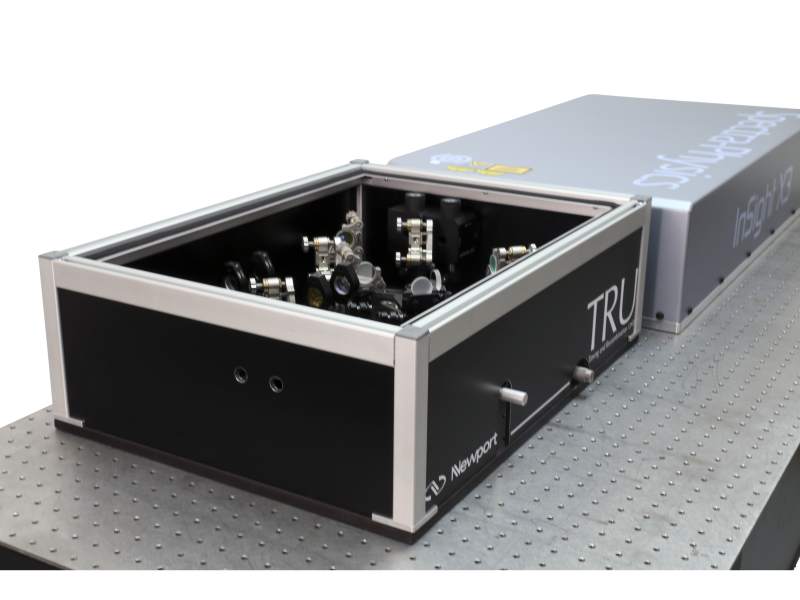
Newport’s new Spectral Focusing Timing and Recombination Unit (SF-TRU) is the second generation of the TRU family, specifically designed for dual-output laser sources, such as the Spectra-Physics InSight® X3+™ and InSight® X3™.
- Flexibly designed to synchronize the two output beams of dual-wavelength, dual-output laser sources
- Includes grating pairs to enable spectral focusing and hyperspectral imaging
- Easily switch between single- to dual-beam, and femtosecond to picosecond output modes, while maintaining beam alignment
- Includes two manual ultrafast variable attenuators
- Includes a resonant EOM for SRS/CARS imaging
- Ultrafast dielectric mirrors (standard) in the tunable beam path See All Features
Specifications
SF-TRU Specifications
| Technical Specs | fs Regime (w/o grating pair) | ps Regime (w/ grating pair) |
|
Fixed Beam Wavelength |
1045 nm | |
| Tunable Beam Spectral Range (single beam) | 680-1300 nm | 790-910 nm |
| Tunable Beam Spectral Range (dual beam) | 750-980 nm | 790-910 nm |
| Raman Shift for CARS, SRS | 600-3800 cm-1 | 1300-3200 cm-1 |
| Fixed Beam Pulse Width1 | <260 fs | 2.2-4.4 ps |
| Tunable Beam Pulse Width | <120 fs | 3.5-7.5 ps |
| Fixed Beam Group Delay Dispersion Range | +12,000 fs2 | -160,000 to -320,000 fs2 |
| Tunable Beam Group Delay Dispersion Range | Provided by DeepSee inside laser 0 to -25,000 fs2 @ 800 nm 0 to -17,000 fs2 @ 900 nm |
Provided by gratings -150,000 to -200,000 fs2 @ 800 nm -240,000 to -320,000 fs2 @ 900 nm |
| Raman linewidth for CARS, SRS | 145 cm-1 | <7 cm-1 |
| Fixed Beam Throughput (pinhole-free silver mirrors)2 | >85% | Additional 40% loss |
| Tunable Beam Throughput (dielectric mirrors option) | >80% | Additional 50% loss |
| Tunable Beam Throughput (pinhole-free silver mirrors) | >70% | Additional 50% loss |
| Attenuation (tunable and fixed beams) | 0-2 OD | |
| Output Polarization (tunable and fixed beams)3 | S- (vertical) standard | |
| Delay Line Maximum Speed | 500 mm/s | |
| Delay Line Travel Range | 125 mm | |
| Fixed Beam Modulation Frequency | 2-4% range of EOM center frequency specified upon ordering | |
| Beam Entrance Height | 4.75 in. (120.7 mm) | |
| Beam Exit Height | 4.44 in. (112.7 mm) | |
| Dimensions (LxWxH) | 30 x 18 x 7.75 in. | |
- Pulse broadening in the fs regime compared to the laser output (<200 fs) is due to the EOM crystal dispersion.
- Specifications only apply to the unmodulated beam. In case of modulated beam, the duty cycle should be taken into account.
- Each beam is equipped with a half wave plate to independently control polarizations before exiting the SF-TRU.
Features
Multiphoton Imaging and Ultrafast Spectroscopy Applications
Developed by scientists in Newport’s Technology and Applications Center (TAC), the SF-TRU is engineered to synchronize the two output beams of dual-output laser sources, facilitating a large variety of single- and dual-beam, multiphoton imaging and ultrafast spectroscopy applications, such as:
- Single- and multi-color (wavelength mixing)
two-photon fluorescence (TPF) - Second harmonic generation (SHG)
- Third harmonic generation (THG)
- Coherent anti-Stokes Raman scattering (CARS)
- Stimulated Raman scattering (SRS)
- Pump-probe
- Transient absorption
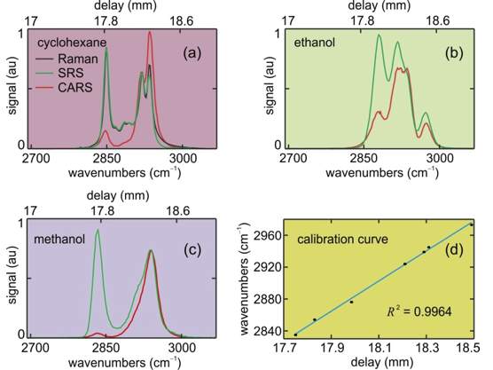
CARS and SRS spectroscopy of liquids in the C-H region
The SF-TRU module enables hyperspectral CARS/SRS imaging with spectral resolution up to 5 cm-1. High spectral resolution is achieved by employing spectral focusing with tunable-distance grating pairs, which, in contrast with fixed-length glass rods, allows matching the spectral resolution and the linewidths of the Raman lines of interest.
(a – c) SRS (green) and CARS (red) spectra of cyclohexane, ethanol and methanol measured by SF-TRU. Chirped pump and Stokes wavelengths are 797 nm and 1041 nm, respectively. The spontaneous Raman spectrum of cyclohexane (black) in (a) shows excellent agreement between spontaneous Raman and SRS spectra. (d) Delay-to-wavenumber calibration curve for hyperspectral imaging obtained from the Raman shift measurements shown in (a – c).
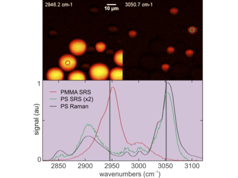
Hyperspectral SRS Imaging in the C-H Region
Top: Hyperspectral SRS images of mixed polymethylmethacrylate (PMMA, large) and polystyrene (PS, small) beads. Two different slices from a stack of a hyperspectral scan are shown. Red and green circles indicate the regions of interest (ROI).
Bottom: SRS spectra of PMMA (red) and PS (green) beads extracted from the hyperspectral scan shown with spontaneous Raman spectrum of PS (black). The vertical bars correspond to the Raman shifts of the frames shown on the top.
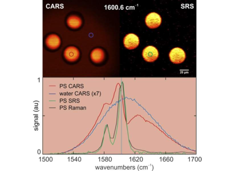
Hyperspectral CARS and SRS Imaging in the Fingerprint Region
Top: Hyperspectral CARS (left) and SRS (right) images of polystyrene (PS) beads. Slices from stacks of hyperspectral scans are shown. Chirped pump and Stokes wavelengths are 893 nm and 1041 nm, respectively. Red, green and blue circles indicate the regions of interest (ROI).
Bottom: CARS (red) and SRS (green) spectra of PS beads and CARS spectrum of water (blue) extracted from the hyperspectral scan shown with the spontaneous Raman spectrum of PS (black). The CARS spectra show the non-resonant background inherent to CARS signals in the fingerprint region. The vertical bar corresponds to the Raman shift of the frames shown on the top.
Two-color (Non-Degenerate) TPF Imaging
Multimodal Imaging of Microstructures Fabricated by Two-photon Polymerization
CARS Imaging of an Optical Fiber
THG Imaging of an Optical Fiber
SF-TRU Components
Inside the SF-TRU, each beam is equipped with an ultrafast variable attenuator for power control. Additionally, each beam path has a telescope to fill the back aperture of the microscope objective and to focus the two beams in the same focal plane. The fixed-wavelength beam at 1045 nm is passed through a high-precision Newport
* EOM resonant frequency should be specified upon ordering.
Resources
Application Notes
Literature
Spectral Focusing Timing and Recombination Unit (SF-TRU) Datasheet(1,004.2 kB, PDF) Timing and Recombination Unit (TRU) Datasheet(926.6 kB, PDF)


