
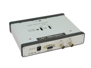
Light Bias Amplifier
Light Bias Amplifier
Our Sample Bias Amplifier is designed for use in QE measurements of various photovoltaic cells where an external light source and/or voltage source is used to bias the cell under test. The Sample Bias amplifier sources current to maintain a fixed voltage bias across the PV cell under test. Generally, QE testing is performed at a zero voltage DC Bias, but with a suitable external low-noise voltage source, it is possible to select a different DC voltage bias for further characterization purposes. This current has a DC component, and an AC component.
- Allows light biasing of PV cells for quantum efficiency measurement
- Allows electrical biasing of PV cells quantum efficiency measurement
- Measure DC component of Irradiance induced Current through BNC connector using a volt meter
- Measure AC component of Irradiance induced Current from the chopped signal using the Merlin lock-in amplifier
- Separate and independent gain settings for AC and DC signals
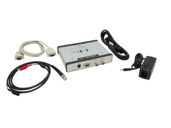
- Two or Four wire operation See All Features
| Compare | Description | Drawings, CAD & Specs | Avail. | Price | ||
|---|---|---|---|---|---|---|
 | 70714Sample Bias Amplifier, QE | In Stock |
Specifications
- TypeSample Bias Amplifier
- Bandwidth4 Hz - 5900 Hz
- Weight0.5 kg
- Dimensions169.3 x 36.2 x 123.8 mm
- AC Gain Temperature Coefficient±35 ppm / °C Max
- DC Gain Temperature Coefficient±25 ppm / °C Max
- DC Gain Accuracy±0.2% for 10 x Gain
- Temperature Coefficient±100 ppm/ °C Max
Features
Measure the AC Component
The AC component is proportional to the chopped light Irradiance from the monochromator, which can be measured at the DB9F connector with a Merlin Digital Lock-in Radiometry System. By measuring the AC component at different wavelengths, one can construct the external and internal Quantum Efficiency curve for photovoltaic cells. The Sample Bias amplifier has individual selectable gains via gain switches on the top of the amplifier for the DC and AC components.
Short Circuit Current
The 70714 Sample Bias Amplifier can provide the short circuit current (Isc) for the photovoltaic device being tested by monitoring the DC output. The Isc is obtained by dividing the voltage at this output to the resistance corresponding to DC gain. All measurements performed using this amplifier can be made in two- or four- wire configurations.


