DynamYX® GT High Throughput Air Bearing Stage
DynamYX® GT High Throughput Air Bearing Stage
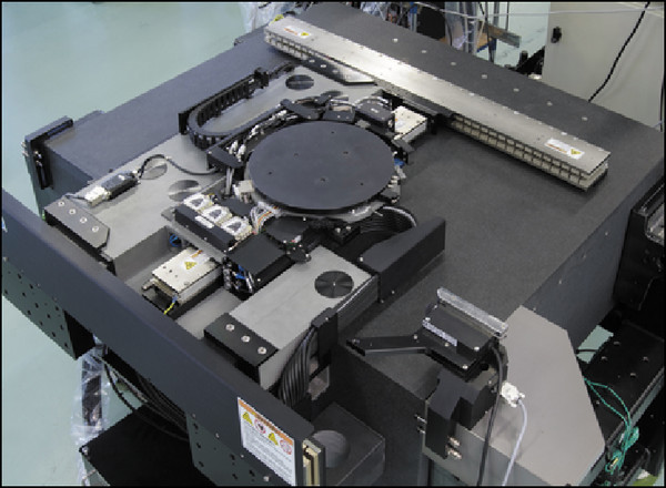
The DynamYX® GT stage is intended for high-throughput applications with aggressive duty-cycles. Featuring an extremely rigid structure and high load capacity air bearings, it provides up to 2G acceleration. They DynamYX GT also has high-efficiency X and Y linear motors with integrated cooling drive moving masses through respective center of gravity locations.
- Designed for high-throughput applications with aggressive duty-cycles
- Extremely rigid structure and high load capacity air bearings provides up to 2G acceleration
- High-efficiency XY linear motors drive moving masses through respective center of gravity locations
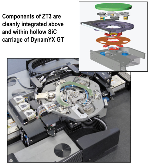
- Available with patented ZT3, Z-Tip-Tilt-Theta stage See All Features
| Compare | Description | Drawings, CAD & Specs | Avail. | Price | ||
|---|---|---|---|---|---|---|
 | DYNAMYX-GTAir Bearing Stage, High-Throughput, DynamYX® GT |
Features
DynamYX® Family of Air-bearing Stages
Linear Motor Drives
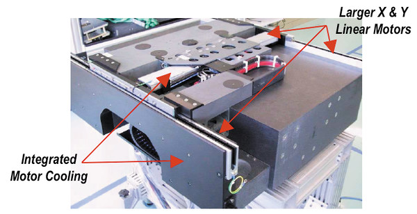
The original DynamYX 300 and DynamYX RS “Reticle Stage” tables are driven by only two Ironless linear motors; one in the X-axis and one for the Y-axis. The rating of each motor is carefully considered based on the intended duty cycle/throughput requirements as to minimize the power dissipation of the system. For even higher throughput requirements, the DynamYX GT and all-new DynamYX Datum incorporate a second X axis linear motor which is driven in open loop mode. Unlike H-bridge air bearing designs which rely on a synchronized servo loop for positioning and stiffness, the monolithic ceramic guide found in all four designs defines the positioning reference and overall stiffness of the positioning elements. Controlling any of the four DynamYX stages is very much like controlling a conventional XY stack with one control signal for X and one for Y. For the GT and Datum stages, a single X-axis control signal is split and fed into two amplifier channels where the output force is biased according to the linear motor ratings and total payload. Most linear motors on the market were designed without focusing on the real needs of precision motion control applications where mass limits and efficiency are most critical. Newport air bearing stages benefit from our commitment to providing the highest possible performance by incorporating motors developed in-house that are optimized for the products and applications they address. Newport’s linear motors have outstanding performance in the areas heat dissipation, time constant, force ripple, and structural integrity. From an efficiency standpoint, the performance of our motors is measured as the steepness per given motor volume where steepness is defined at the heat dissipated by a motor when delivering a given force (F2/W) and volume is simply the motor cross-section multiplied by the coil length. In situations where the rms acceleration values are extremely high and any heat loss is a problem, our motors feature sealed-forced air or recirculating water methods of cooling.
Z-Tip-Tilt-Theta stage
Position Feedback
The positioning loop on DynamYX may be closed using a single linear encoder for each axis. As shown in the adjacent illustration, the encoder measuring positions are closely located to the substrate’s surface reducing the already minimal abbe offset affect. For the X-axis, the linear scale is typically mounted to the underside of the bridge structure with the read-head in-line with the system’s optical path and affixed to the moving ceramic guide. System architectures that do not allow this configuration can be accommodated by mounting the X-axis scale to a supplementary SiC spar located at the rear side of the system. The Y-axis has its scale mounted to a small SiC bracket on the moving carriage. The read head is fixed to the arm of the L-shape structure. Read-heads which have fixed positions relative to the tool’s optical path are beneficial in optimizing precision. With an encoder signal period of 2mm, resolutions down to 0.1nm are possible with Newport’s XPS or SPS controllers each with internal 20,000 times interpolation. Equipped with linear encoders the DynamYX is an extremely accurate and very repeatable platform allowing for very high accuracy through error mapping. The geometric stability of the ceramic elements of these stages results in systems that can be mapped once at our factory then, upon installation, only require a simple length calibration to compensate for uniform thermal expansion. For applications where the accuracy requirements exceed the capabilities of error compensation, or in certain scanning modes where the absolute position of the stage must be the basis of a very precise trigger or latch, linear encoders must yield to laser interferometers which are also part of our offering.