200 kHz Adjustable Fiber-Optic Receivers
200 kHz Adjustable Fiber-Optic Receivers
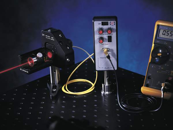
These 200 kHz FC/PC fiber-optic receivers are the ideal optical front ends for systems requiring low-noise input with modest bandwidth. They have been engineered to eliminate most common sources of noise and drift. Battery powered, they connect to other instruments with a single coaxial cable, thus eliminating the possibility of ground loops, and have enough gain to pick up even very weak signals.
- Adjustable high-pass and low-pass filters
- Variable-gain transimpedance amplifier
- Easily set to either AC or DC coupling
- Silicon or InGaAs detectors See All Features
| Compare | Description | Drawings, CAD & Specs | Avail. | Price | ||
|---|---|---|---|---|---|---|
 | 2001-FC-M | In Stock FREE 2-day shipping on thousands of products on Newport.com Learn More | ||||
| 2011-FC-M | In Stock FREE 2-day shipping on thousands of products on Newport.com Learn More |

Specifications
- Detector Diameter2001: 0.9 mm
2011: 0.3 mm - Detector Material2001: Silicon
2011: InGaAs - Detector TypePIN
- 3 dB BandwidthDC to 200 kHz
- Fiber-Optic ConnectorFC/UPC
- Maximum Transimpedance Gain18.8x106 V/A
- Rise Time2 µs
- Saturation Power2001: 10 mW @ 850 nm
2011: 10 mW @ 1600 nm - Output ConnectorSMA
- Output Impedance16 Ω
- Power RequirementsTwo internal 9V batteries
Features
Silicon or InGaAs Versions
The silicon photodetector version (2001) has a 0.9 mm diameter PIN detector that provides wavelength coverage from 300-1050 nm. The InGaAs photodetector version (2011) has a 0.3 mm diameter PIN detector that provides wavelength coverage from 900-1700 nm.

Adjustable high-pass and low-pass filters
Independent control of the low and high-frequency corners allows you to reject unwanted noise effectively. The single-pole filters provide a slope of –6 dB/octave with less than 90° phase shift. The DC÷30 setting prevents your signal from going off-scale due to DC amplitude fluctuations, without attenuating fast signals. The high-pass filter can be adjusted to eliminate residual 60-Hz noise, and the independent low-pass filter can be set to dampen noisy signals. The upper left knob adjusts the low-frequency corner and the upper right knob adjusts the high-frequency corner. The corner frequency increases by a factor of three with each full clockwise turn. The photoreceivers have ten settings for each frequency corner, creating a wide variety of frequency responses.
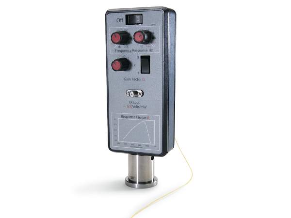
Set to Either AC or DC Coupling
Set the low frequency corner knob to DC, and the detector operates in the DC coupled mode. At all other settings, the detector operates in the AC coupled mode.
Variable-gain Transimpedance Amplifier
Variable gain of up to 90 dB in 10-dB steps gives you a useful input range from 1 pW to 10 mW. For small signals requiring 80-dB or greater gain, the maximum bandwidth is reduced from 200 kHz to 20 kHz. Ample +/- 6 V voltage output can be generated without saturation.
Flexibility & High Performance for a Wide Range of Applications
These photoreceivers can be used for many different applications, including aligning fibers in high-speed-photodetector test and pigtailing setups. They can also be employed as low-noise, DC-coupled photoreceivers/preamplifiers in servo-control systems requiring near-zero phase shifts at up to 100 kHz. Or they can be used in lock-in amplifier systems to take advantage of their shot-noise-limited performance and 90-dB maximum gain. And by correlating their output voltages to a calibrated power meter, these photoreceivers can also serve as sensitive power sensors.