Application Note:
Practical Uses and Applications of
Electro-Optic Modulators
Overview
Electro-optic amplitude and phase modulators allow you to control the amplitude, phase, and polarization state of an optical beam electrically. For instance, in communications systems, these modulators impress information onto an optical frequency carrier. Unlike direct modulation of the laser itself, external modulators do not cause any degrading effects on laser linewidth and stability. In measurement systems, amplitude modulators can be used as actuators to hold the intensity in a laser beam constant, or as optical choppers to produce a pulse stream from a CW laser beam. Phase modulators are used to stabilize the frequency of a laser beam, or to mode-lock a laser.
There are basically two types of modulators: bulk and integrated-optic. Bulk modulators are made out of discrete pieces of nonlinear optical crystals and are typically used on a lab bench or an optical table. They feature very low insertion losses, and high power-handling capability. Integrated-optic modulators, which will not be discussed here, use waveguide technology to lower the required drive voltages, are wavelength specific. Unlike bulk modulators, these modulators are fiber pigtailed and compact. After a brief discussion on the electro-optic effect, this application note will describe the use and application of bulk modulators.
The Electro-Optic Effect
The linear electro-optic effect is the change in the index of refraction that is proportional to the magnitude of an externally applied electric field.1 The effect of an applied electric field on the index of refraction, seen by an optical beam polarized in an arbitrary direction in a crystal, is described by a third-rank tensor.2 Ignoring the vector nature of the physical quantities, the effect of an external electric field on the index of refraction of a crystal has the form
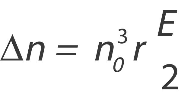
where Δn is the change in the index of refraction, no is the unperturbed index of refraction, r is the appropriate element in the electro-optic tensor, and E is the applied electric field. This effect is small even in the few crystals with large electro-optic coefficients. For example, an electric field of 106 V/m applied to a crystal of lithium niobate will produce a fractional index change of roughly 0.01%. It is rare to see fractional index changes greater than 1%.
Bulk Modulators
New Focus™ manufactures electro-optic amplitude and phase modulators using lithium niobate, LiNbO3, and KTP—two crystals with high electro-optic coefficients and good optical and electrical properties. These crystals are grown in large, low scatter-loss boules, and have a wide transparency window. They are also non-hygroscopic so they can be left on an optical table for indefinite periods without being in a sealed enclosure.
Phase Modulation
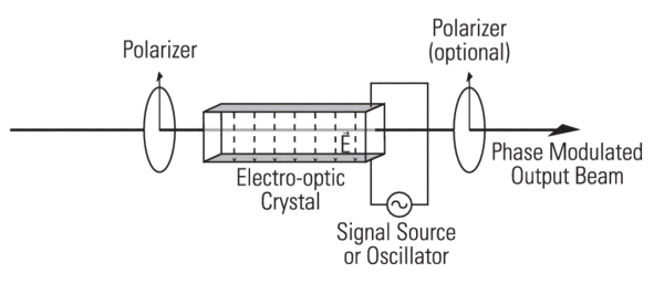
The phase modulator is the simplest electro-optic modulator. Here, an electric field is applied along one of the crystal's principal axes.3 Light polarized along any other principal axis experiences an index of refraction change, hence an optical path length change, that is proportional to the applied electric field. The phase of the optical field exiting from the crystal therefore depends on the applied electric field. The most common bulk phase modulator is the transverse modulator, as shown in Figure 1, which consists of an electro-optic crystal between parallel electrodes. These modulators develop large electric fields between the electrodes while simultaneously providing a long interaction length, l, in which to accumulate phase shift. The optical phase shift, Δφ, obtained from applying a voltage, V, between the electrodes is given by
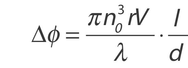
where λ is the free-space wavelength, and d is the electrode separation. A commonly used figure of merit for electro-optic modulators is the half-wave voltage, Vπ. It is defined as the voltage required to produce an electro-optic phase shift of 180°. Substituting into the preceding equation yields
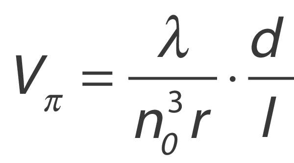
for a transverse phase modulator.
It is important to note that the properties of a phase-modulated optical beam do not differ in any way from those of any other phase-modulated carrier wave.4 Most importantly, phase modulation cannot be separated from frequency modulation. The instantaneous frequency of a periodic signal is defined as the time derivative of the overall phase of the signal. Therefore, for a phase-modulated signal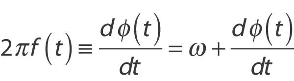
where f(t) is the instantaneous frequency, φ(t) is the signal's global phase, and ω is the optical frequency. Given a phase modulation φ(t)=msinΩt where m is the phase-modulation index, sinusoidal phase modulation results in sinusoidal frequency modulation at a fixed frequency , but with a 90° phase lag and a peak-to-peak excursion of 2mΩ. The phase-modulated field amplitude can be represented as a set of Fourier components in which power exists only at the discrete optical frequencies ω±kΩ.
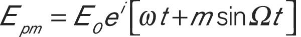
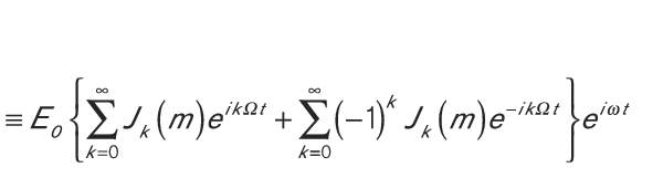
where k is an integer, m is the phase-modulation index (modulation depth) and Jk(m) is the ordinary Bessel function of order k. In the case of small modulation index, m<<1, then only the k=0 and k=1 terms are significant and the expansion reduces to
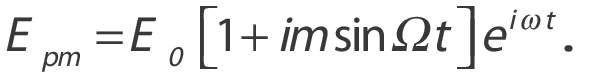
Here, most of the optical power resides in the Fourier component, called the “carrier,” at frequency ω, with a small amount of optical power residing in the two first-order sidebands at frequencies ω±Ω. This frequency-modulating property makes phase modulators useful in laser mode-locking.5
Amplitude Modulation
To understand the operation of an electro-optic amplitude modulator, let's first consider an electro-optic waveplate. Suppose an optical beam, polarized at 45° to the crystal's principal axes, travels parallel to the third axis of an electro-optic crystal. With no applied field, the crystal is generally an arbitrarily retarding, multiple-order waveplate.6 When an external electric field is applied, the electro-optic effect changes the indices of refraction along the two crystal directions to a different degree, thereby changing the retardation of the effective waveplate.
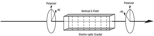
The geometry of a simple amplitude modulator, as shown in Figure 2, consists of a polarizer, an electro-optic crystal cut for zero retardation, and an analyzer. The input polarizer guarantees that the optical beam is polarized at 45° to the crystal's principal axes. The crystal acts as a variable waveplate, changing the exit polarization from linearly polarized (0° rotated from the input) to circularly polarized, to linearly polarized (90° rotated), to circular, etc., as the applied voltage is increased. The analyzer transmits only the component of the exit polarization that has been rotated, thereby producing a total transmission of 0, 0.5, 1, and 0.5 respectively. The relationship between the transmission and applied field is not linear but rather has a sin2 dependence. To obtain linear amplitude modulation, these modulators are often biased at 50% transmission and only operated with small applied voltages. Two ways to bias the modulators are by one, adding a DC voltage through a bias tee, or two, adding a quarter-wave plate before the analyzer. The voltage required to bias the modulator at 50% transmission without a quarter-wave plate is the quarter-wave voltage of the modulator. It has a similar form to the quarter-wave voltage of the transverse phase modulator.
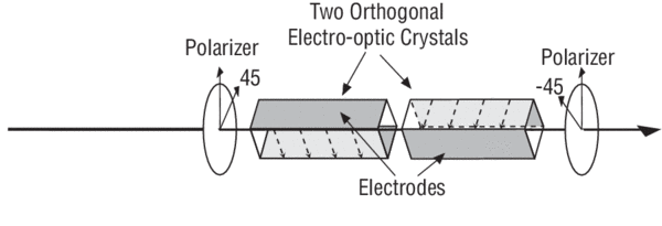
This simple geometry is not practical with most electro-optic crystals, due to the temperature dependence of these crystals' birefringence. This dependence introduces a temperature-dependent waveplate into the modulator. Consequently, the transmission of an uncompensated modulator using birefringent nonlinear media (such as LiNbO3) will exhibit substantial thermal drift. This temperature sensitivity can be overcome by either stabilizing the temperature of a single-crystal modulator, or by using two identical crystals. The second scheme employs two equal-length crystals placed optically in series with their principal axes rotated 90° with respect to each other, as seen in Figure 3. The optical beam's polarization components therefore travel equal path lengths in each of the two index regions, which leads to a structure with zero birefringence, independent of temperature. Thermal drift limits the usefulness of a phase modulator, which is typically made out of a single crystal.
Practical Limitations
There are several practical limits on the performance of these devices. Mainly, the optical power handling capability of LiNbO3 is limited by an effect known as photorefractive damage. Although this effect is sometimes useful (as in holographic data storage) and does not permanently damage the crystals, it can degrade the performance of a modulator. A modulator with a photorefractively damaged crystal will distort an optical beam passing through it.7 The best way to avoid photorefractive damage is to keep the optical intensity below the specified limit for the modulator. Since the photorefractive effect is highly wavelength dependent, modulators can handle correspondingly higher powers at longer wavelengths. New Focus also uses LiNbO3 that has been doped with magnesium-oxide (MgO). This new material exhibits far superior power-handling capability.
Another limitation results from the fact that all materials with nonzero electro-optic coefficients are also piezoelectric. This means that the same electrical signal that produces phase modulation also generates vibrations. Strains induced by these vibrations alter the indices of refraction via the elasto-optic effect. These vibrations can cause unwanted amplitude modulation or beam displacements at the modulation frequency. The piezoelectric constants of LiNbO3 are fairly weak, and typically do not affect the performance of the crystals as long as the mechanical resonance frequencies (typically between 1 and 10 MHz) are avoided. New Focus will not ship single-frequency modulators tuned near a piezoelectric resonance.
A third limitation when using a phase modulator is residual amplitude modulation. An ideal phase modulator should not modulate the intensity of an optical beam. Amplitude modulation will be induced by sources of back-reflection placed after the phase modulator. Back-reflections result in weak étalons which will alter the harmonic content of the modulated optical beam by introducing a measurable amplitude modulation component onto the beam. Unwanted amplitude modulation can be minimized by properly aligning the input polarization state to the principal axis of the modulator, which is vertical in the case of New Focus™ modulators. You can further reduce residual amplitude modulation by using a collimated optical beam positioned down the center of the modulator. To enable quick and easy alignment of its modulators, New Focus offers the Model 9071 tilt aligner.
Broadband Modulators
New Focus offers modulators designed to modulate either the amplitude or phase of linearly polarized light over a wide bandwidth, from DC to roughly 100 MHz, with a relatively low drive voltage. The electrical input impedance of these devices in this frequency range is dominated by the capacitance of the electro-optic crystal. This capacitance ranges from 10 pF for the Model 4104 amplitude modulator to 30 pF for the Models 4002 and 4004 phase modulators. Signal generators and frequency synthesizers typically have 50-Ω output impedances, and are not optimized for driving capacitive loads. However, since 30 pF is a fairly small capacitance, most signal generators are adequate drivers at low frequencies (<10 MHz) and small signal levels. High-voltage amplifiers optimized to drive capacitive loads can also be used to effectively drive modulators.
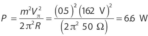
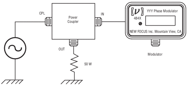
At high frequencies, the impedance mismatch between the cable carrying the modulation signal and the modulator causes a fraction of the RF signal to be reflected back toward the source.8 A directional coupler inserted between the source and the modulator, as shown in Figure 4, can be used to redirect the reflected power to a matched terminator and thereby protect the signal source. Terminating the line driving the modulator with a 50-W load in parallel with the modulator input is an easy way to improve the system's impedance match. At drive frequencies greater than 100 MHz for phase modulators and 200 MHz for amplitude modulators, the RC pole created by this termination will reduce the response to the drive signal by 20 dB per decade. Since the modulators dissipate a minimal amount of power, it is important that all terminators chosen are rated to handle the maximum power output of the signal source or power amplifier. For example, to sinusoidally modulate the phase of an optical beam with a peak phase excursion, m, of 0.5 radian in a 50-Ω system requires an electrical power with a Model 4002 phase modulator. This high power requires the use of power amplifiers and special terminators.
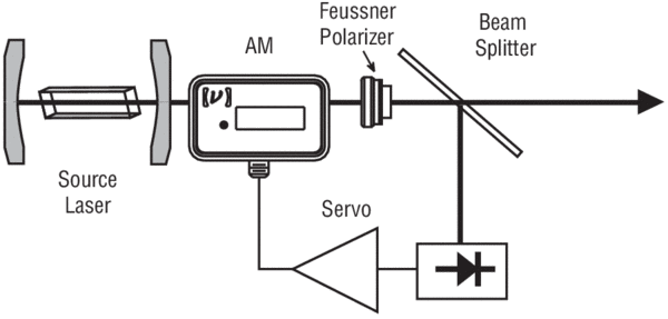
The advantage of a broadband modulator is the flexibility it provides the user to select any modulation frequency, or even to modulate with nonsinusoidal waveforms. Applications where this is important include optical chopping, and short-pulse mode-locking. Another common use for an amplitude modulator is as the actuator in an amplitude stabilizer as shown in Figure 5. Here, a photodetector measures a portion of the laser intensity which the servo uses to adjust the transmission of the amplitude modulator. An important consideration in this application is the nonlinear response of the modulator. The changing slope of the modulator's response to input voltage leads to a change in the closed-loop transfer function which could destabilize the feedback loop.
Resonant Modulators
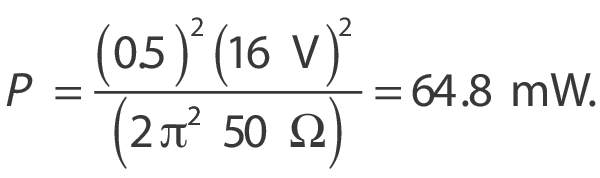
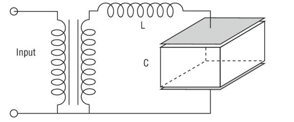
Many applications require modulation at a single, fixed frequency. The frequency required in the specific application can vary from a few kilohertz to many gigahertz. In these cases, true impedance matching can be achieved, and the required drive voltage can be reduced, by using a resonant circuit. The simplest type of resonator is the LC tank, shown in Figure 6. In this circuit, a modulator crystal and a low-loss inductor are used to form a series resonant circuit. On resonance, the resonant circuit looks like a small resistor whose value depends on the inductor's losses. The transformer is used to match this resistance to the 50-Ω driving impedance. By impedance matching to the source, and using low-loss components, the voltage across the capacitor can be more than ten times greater than the input voltage, leading to reduced half-wave voltages when compared to a broadband modulator. This reduced voltage requirement is made possible by the energy storage properties of the resonant circuit. For example, if one used a Model 4001 resonant phase modulator to produce a 0.5-radian modulation as before, the power required would only be
Two factors limit the performance of the lumped-element resonator. The first is the power-handling capabilities of the inductor. Saturation of the inductor core places a limit on the RF-input power that can be used to modulate the optical beam. Also, most of the power dissipation occurs in the inductor and excessive input power will burn it out. Secondly, at frequencies greater than 50 MHz, ordinary lumped circuit elements are difficult to make. Circuits with dimensions comparable to the operating (RF) wavelength are efficient radiators, and therefore very difficult to analyze. Furthermore, conventional wire circuits tend to have a high effective resistance due to radiative energy loss as a result of the skin effect. Enclosures completely surrounded by conducting metal confine electromagnetic fields and furnish large areas for current flow, simultaneously eliminating radiation and high-resistance effects. Such cavities have natural resonant frequencies, and can be used to replace resonant circuits at high frequencies.9 New Focus offers cavity-resonant, single-frequency modulators out to 10 GHz, a frequency limited by the increasing RF losses in the electro-optic material itself.10
Applications for single-frequency modulators are quite varied. In the audio regime, these modulators are used in fiberoptic sensor and interferometric applications as well as in low-frequency lock-in detection schemes. Medium- to high-frequency modulators (to 250 MHz) find applications in mode-locking (AM and FM), laser stabilization, phase-sensitive detection, and pump-probe detection schemes. Modulators with frequencies to 10 GHz find applications in FM spectroscopy, laser stabilization, and laser linewidth-broadening experiments.
Summary
Bulk electro-optic modulators find uses in a wide variety of applications. They make it easy to modulate the amplitude or phase of an optical signal up to 10's of gigahertz. Bulk modulators are well-suited for applications with high optical powers or broad spectral bandwidth requirements. Understanding how these modulators work and how to work with them will allow you to make your measurements and develop your systems in the most efficient and accurate way.
References
- For further information on the electro-optic effect see A. Yariv, Optical Electronics, 3rd edition, Ch. 9, or A. Yariv and P. Yeh, Optical Waves In Crystals, New York: John Wiley Sons, 1984.
- For example, Yariv, pp. 280–283.
- For more background on birefringent crystals, see New Focus™ Application Note 3 on polarization.
- See the analysis in A. B. Carlson, Communications Systems, Ch. 6.
- An introduction to laser mode-locking is found in A. Siegman, Lasers, Ch. 27.
- Waveplates are described in New Focus Application Note 3 on polarization.
- See T. J. Hall, R. Jaura, L. M. Connors, and P. D. Foote, “The Photorefractive Effect—A Review,” in Prog. Quantum Elect. 10, pp. 7–146.
- For an introduction to transmission line theory, D. Cheng, Field and Wave Electromagnetics, Ch. 9.
- Resonant cavities are discussed in S. Ramo, J.R. Whinnery, and T. Van Duzer, Fields and Waves in Communication Electronics, 2nd edition, Ch. 10.
- For more background on high-frequency modulators, ask for a reprint of T. Day, Laser Focus World, “Single Frequency Bulk Electro-Optic Modulators.”