To detect fluctuations in the laser frequency, a highly stable reference is needed for comparison. One common way in which this is achieved is by using a high-finesse Fabry-Perot cavity, constructed in such a way as to provide the necessary stability over the time scale of interest. The mth resonant frequency of a Fabry-Perot cavity (νm), determined by the cavity length L as: νm = m (c ∕ 2L), can be extremely sharp when low-loss, high reflecting mirrors are used8. Although mechanical cavities may drift on longer time scales, they can provide very high short-term stability (~ seconds). This stability can be taken advantage of due to a combination of a sharp cavity resonance and a linear response to the incident optical field. Unlike the nonlinear response of atomic transitions that can saturate, the signal from the reference cavity can ideally be increased until the signal-to-noise ratio (SNR) of the detected cavity resonance is sufficient to provide the needed stability for the laser.
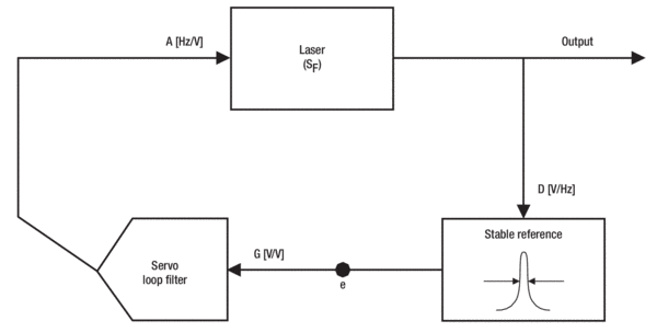
To tightly lock the laser frequency to a resonance of the Fabry-Perot cavity, the resonance must be detected quickly and with a high SNR. This is perhaps the most critical part of the feedback loop, as it ultimately determines the performance of the system. The difference between the laser frequency and cavity resonance is converted into a voltage, with a discriminator coefficient D given in units of V/Hz. The discriminator voltage, or “error signal”, can be obtained by several methods. The simplest and most straightforward approach is to lock to the side of the cavity transmission fringe. The side-fringe locking technique uses the slope on either side of the transmission peak to convert frequency fluctuations of the laser into amplitude fluctuations, which are subsequently detected by a photodiode.
Although easy to implement, the technique suffers from several drawbacks. First, amplitude modulation (AM) from the laser directly couples into the error signal; the feedback loop cannot tell the difference between frequency modulation (FM) and AM. Changes in the laser amplitude will therefore be “written” onto the laser frequency. Secondly, due to the photon-lifetime of the Fabry-Perot cavity8, fast frequency fluctuations of the laser will not be detected in transmission through the cavity. A final limitation is the narrow locking range. A small deviation from the locking point can cause the laser to unlock if the frequency momentarily shifts across the cavity transmission peak. The last two limitations present a particularly troubling tradeoff; high-finesse cavities are desirable so as to provide a narrow linewidth for laser stabilization, yet will simultaneously limit the bandwidth of the feedback loop and reliability of the lock9.
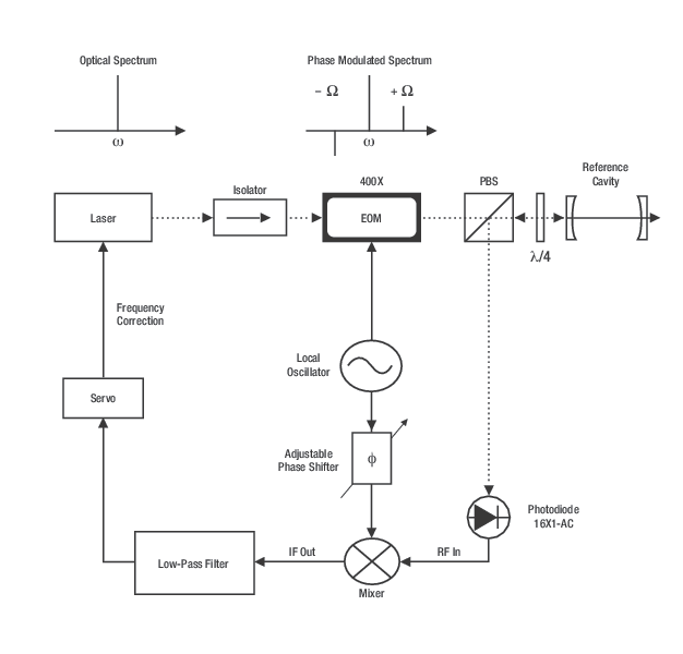
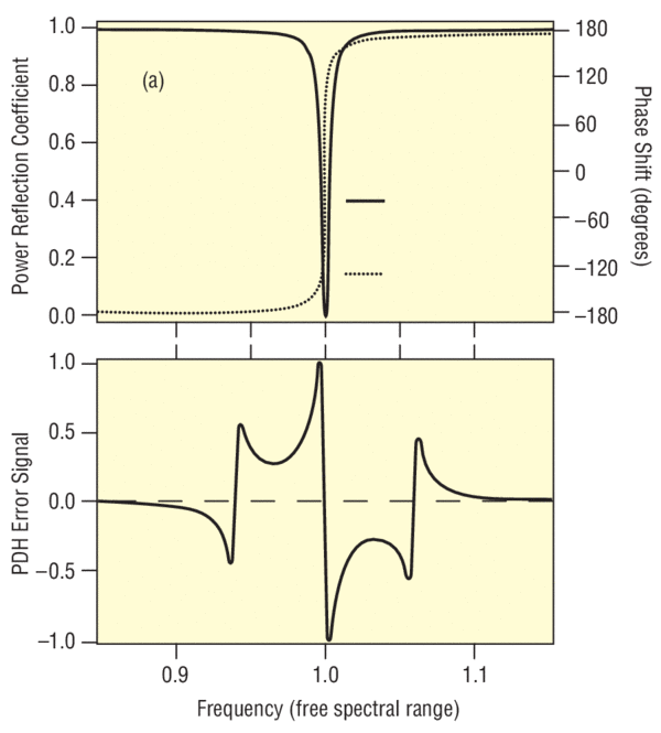
A better method, “Pound-Drever-Hall” (PDH) stabilization, is easy to implement and avoids all the above-mentioned complications9. PDH stabilization is closely related to the powerful technique of modulation-spectroscopy used for the sensitive detection of atomic and molecular transitions10. Pound11 first proposed this technique for the stabilization of microwave oscillators by introducing phase modulation at a frequency several times greater than the resonance linewidth. To avoid the limitations of AM on the laser beam, PDH stabilization relies on the rapid modulation of a laser's frequency to quickly probe both sides of the cavity resonance. If the resonance information is detected at a sufficiently high modulation frequency, amplitude fluctuations can be reduced to their shot-noise limited level. In addition, PDH stabilization utilizes the light reflected from the Fabry-Perot cavity. This is advantageous since the reflected light will be at a minimum on resonance decoupling AM noise from the error signal. Another important aspect of the PDH technique is that the response will not be limited by the cavity lifetime, allowing for greater bandwidth in the feedback loop. In the next section, we will describe the details of this technique and its simple implementation.
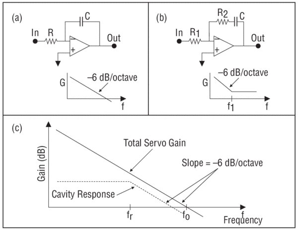
Once the error signal (e) is generated, it is sent through the servo “loop filter” to ensure the feedback is applied to the laser with the appropriate phase. Due to the finite time delay in the feedback loop, all Fourier frequencies of the error signal cannot be sent back to the laser with the proper phase. The frequency-dependent voltage gain (G, with units of V/V) must therefore roll off toward zero at some frequency to prevent positive feedback. After the signal is conditioned by the loop filter, the correction voltage is finally applied to the actuator, characterized by a coefficient A in units of Hz/V. The frequency range over which the actuator exhibits a flat frequency response to the applied correction signal usually determines the maximum bandwidth of the servo loop. For instance, a piezo-mounted cavity mirror can be used as an actuator to correct the laser frequency. These often have a resonant frequency on the order of a few kHz. Thus the servo bandwidth needs to remain much less than this in order not to excite the piezo resonance. New Focus TLB-7000, TLB-6000 and TLB-6300 series lasers provide convenient inputs for linear frequency tuning up to several kHz. With appropriate servo designs, these can be used simultaneously to provide extremely fast laser-frequency corrections5.
The New Focus™ StableWave™, Velocity™ and Vortex™ series lasers offer narrow instantaneous linewidths. They are well suited for precision spectroscopy and can be easily stabilized to a high-finesse cavity using the PDH locking technique. Many of the critical components needed for PDH laser stabilization are also available from New Focus. An experimental layout to implement PDH laser frequency stabilization is shown in Figure 2.