Optical Fiber Alignment
Key Motion Parameters for Fiber Alignement
When using motion control systems for fiber alignment, the motion parameters considered for each axis critically affect the alignment process. The following are the primary parameters for consideration when selecting a motion controller for the location of peak power in fiber alignment procedures:
- Minimum Incremental Motion (MIM) - This is the smallest increment of motion that a device can consistently and reliably deliver. It should not be confused with resolution, which is based on the smallest controller display value or smallest encoder increment. Rather, MIM is the actual physical performance of the controller that enables adjustment of the fiber position while searching for the position at which peak power is achieved. MIM of a motion controller can range from 100 nm to 1 nm. While a smaller MIM may align the fiber closest to the maximum peak power, this ability is achieved at significant costs in terms of alignment speed and power increments. XMS stages (Figure 3) are designed with optimized MIM and speed characteristics. They are capable of 1 nm MIM and 300 mm/s speed, making them ideal stages for alignment applications.
- Repeatability - The repeatability parameter defines a motion control systemÕs ability to repeatably position. It can be unidirectional (always approaching the target position from the same direction) or bidirectional (approaching the target position from either direction). Bi-directional repeatability typically ranges from 1 µm to a few nm in fiber alignment systems. This parameter is important for quickly finding the peak power location for similar device designs. The XMS stage shown in Figure 3 has 80 nm bi-directional repeatability.
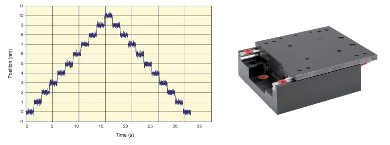
- Position stability - Position stability is a measure of the motion system's capability to stay at a position within a defined window of time and error. Aligning fibers for assembly steps such as bonding relies on the positional stability of the fibers after the peak power has been located. Position stability requirements can range from 0.5 µm to a few microns. Figure 4 shows the step and settle performance of an MKS stage 250 ms after being moved. This stage exhibits less than 20 nm variation in position stability after settling.
- Other Motion Parameters - Other parameters that influence the effectiveness of a motion control system include: axis alignment, location of the gimbal point, system stiffness, pitch/yaw, thermal considerations, fixture design, Abbe error, etc. Details regarding the fundamentals of motion control can be found in Chapter 1, Section III.F.1. MKS also has an available metrology primer that provides further information on this topic.
Search Algorithms
In addition to understanding critical motion parameters, efficient fiber alignment requires the selection of a positional search algorithm appropriate to the application and to the step in the alignment procedure. Specific search algorithms are available for finding the first light, i.e., the periphery of a light beam, after which different algorithms that are faster and more precise are used to find the peak power location. The choice of the second algorithm depends on whether the beam has a Gaussian distribution or top hat profile with multiple peaks. Some algorithms can be used to profile both types of beams and can also be used in parallel.
Algorithm Usage
|
Photonic Device Search Algorithm (PDSA) API |
Beam Profile: Gaussian or Single Peak |
Beam Profile: Plateau or Multiple Peaks |
Find First Light |
Find Peak Power |
Find Peak Power along Beam Axis (Z) |
Stop when Threshold Reached |
Max Number of Axes |
|---|---|---|---|---|---|---|---|
|
Axis by Axis |
X | X | 6 | ||||
|
Dichotomy |
X | X | 6 | ||||
|
Escalade (Continuous) |
X | X | 3 | ||||
|
Escalade (Square) |
X | X | X | 3 | |||
|
Raster |
X | X | X | X | 2 | ||
|
Spiral (Continuous) |
X | X | X | 2 | |||
|
Spiral (Square) |
X | X | X | 2 |
Raster Scan
This is the simplest search method. It scans along one axis and indexes by a certain distance along another axis, then repeats the cycle. It is one of the quickest methods for finding the first light of the beam. The concept is shown in Figure 1 where the green line shows how the raster proceeds.
- Advantages
- Used to find First Light or Peak Power
- Stops when Threshold is reached
- Disadvantages
- Limited to 2 axes
- Start-stop motion (not continuous)
Spiral Scan
Executes an outward spiral (Continuous-PVT or Square) until reaching the power threshold (Square only) or return to the highest power position after completing the spiral.Figure 5 illustrates this first light method, which tracks in the general area of the beam using a spiral motion by synchronizing the motion of the X and Y axes.
- Advantages
- Used to find First Light or Peak Power
- Continuous Spiral provides smooth motion
- Square Spiral stops when Threshold is reached
- Disadvantages
- Continuous (PVT) must complete entire trajectory/spiral and does not stop when Threshold is reached
- Limited to 2 axes
After first light has been located, other algorithms are available that can find the peak power location:
Hill Climb
This is a 2D search method based on finding the highest power within a certain path (Figure 6). The direction of the climb favors the location of the higher power region. The hill climb method is most effective when the beam has a Gaussian profile and when power quickly increases. The hill climb method, by itself, is not effective in finding peak power with flat beam profiles.
Axis by Axis
Execute a relative move in both directions, then returns to the location of the highest power found. Then the same process is repeated for the next axes.
- Advantages
- Search one axis or multiple axes (6 DoF)
- Can be repeated (with speed or search distance reduced) to pinpoint peak power location
- Best for gaussian beam profile or single peak
- Disadvantages
- First Light should be found first
- Limited when peak power is a plateau or has multiple peaks
- Algorithm does not stop when Threshold is reached, but after motion is complete, returns a value if it was reached
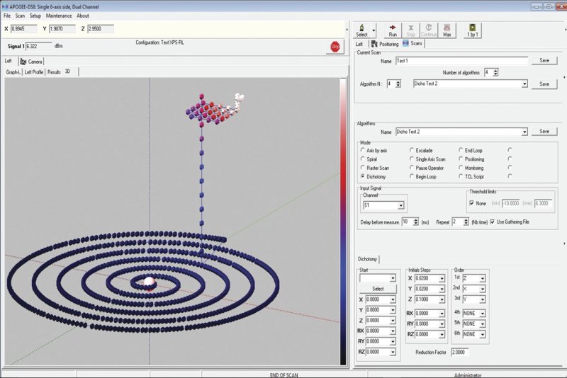
Dichotomy
Similar to “Axis by Axis”, but process repeated with smaller steps until reaching the minimal step size. Starting with large increments, a dichotomy search (Figure 8) initially searches one axis at a time until a peak is identified. The search then returns to the first peak. Within this first peak, another search cycle is performed using finer steps to find the maximum peak location. Starting step size is reduced by defined ReductionFactor and continues until MaxReductionFactor is reached.
- Advantages
- Saves time by automatically reducing the step size before re-running Axis by Axis.
- Search one axis or multiple axes (6 DoF)
- Best for gaussian beam profile or single peak
- Disadvantages
- First Light should be found first
- Limited when peak power is a plateau or has multiple peaks
- Only step size, not speed or other parameters, are reduced
Escalade
After completing a first spiral search, a half size second spiral is executed at a different Z position, then stages move step by step (by a quarter of initial Z motion) on the axis defined by the two spiral peak power locations until reaching a maximum or the threshold. Spiral search can be Continuous-PVT or Square.
- Advantages
- Finds Peak Power along X, Y, and Z (optical) axes
- Disadvantages
- Continuous (PVT) must complete entire trajectory/spiral and does not stop when Threshold is reached
- Algorithm only works on X, Y, and Z axes

For additional insights into photonics topics like this, download our free MKS Instruments Handbook: Principles & Applications in Photonics Technologies
Request a Handbook