Fiber Alignment Solutions
For over 40 years, MKS has provided thousands of fiber alignment systems for optical applications in a variety of markets. We are one of the major players in fiber alignment during the telecom buildup. With deep understanding of challenges faced in fiber alignment systems, we not only offer a full range of products for fiber alignment, but also partner with each customer to discover the best solution for their applications.
| Challenges in Fiber Alignment | MKS Solutions |
|---|---|
| Maximizing transmission through fiber or waveguide | Sub-micron and nanometer scale positioners |
| Increasing speed of process | API algorithms, fast detectors & fast positioners |
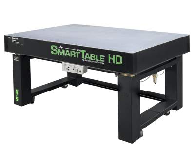
| Stability of system | Vibration control & robust positioners |
| Multiple alignments | High performance motion controllers & highly repeatable positioners |
| Building the optimal system | Applications engineering expertise & full range of products |
MKS Fiber Alignment Products
Check out MKS Recommended Fiber Alignment Products to build a fiber alignment system that best fits your application.
Typical Fiber Alignment System Requirements
| R&D | Limited Automation | Low Volume | High Volume | |
|---|---|---|---|---|
| Alignment Accuracy & MIM | 1 µm | 200 nm | 100 nm | 50 to 100 nm |
| Speed/Cycle Time | Minutes (usually user-dependent) |
Seconds or minutes (can be user-dependent) |
Several seconds | Few seconds |
| Repeatability | Not as critical (user-dependent) |
Hundreds of nm | Hundreds of nm | <100 nm |
| MTBF/Reliability | Not as critical | Thousands of hrs | Thousands of hrs | >10,000 hrs |
Fiber Alignment Motion Systems
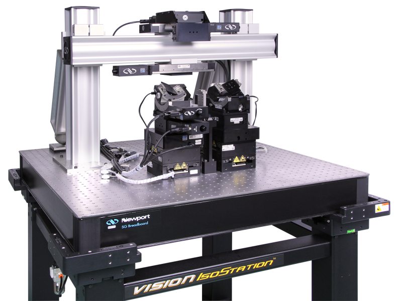
Motion control systems can be customized in many ways, depending on the DUT. Figure 1 shows different configurations of fiber alignment systems, ranging from a simple, single-channel, single-side setup to a more complex double-sided, multiple-channel setup that includes machine vision, adhesive delivery/curing, and pick and place. Other setups may have horizontal and vertical beam inputs and outputs. Every configuration requires a unique set of motion products, depending on the performance required for that device. The basics of motion control systems can be found in Motion Control Systems.
Different configurations are available for the motion control systems used in fiber alignment, ranging from simple manual stages suitable for small scale and R&D applications to full-featured automated production systems with high precision motorized stages, pick and place automation, dispensing and curing systems, machine vision, etc. The following systems illustrate, in part, this range of configurations.
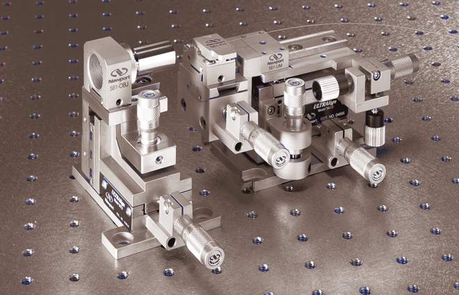
Fiber Alignment in Scientific Research
Up to 6 DOF manual alignment system features off the shelf products and is ideal for scientific research in university laboratories.
Single-End R&D Fiber Alignment System
Automated alignment for R&D or production, this system features off the shelf products.
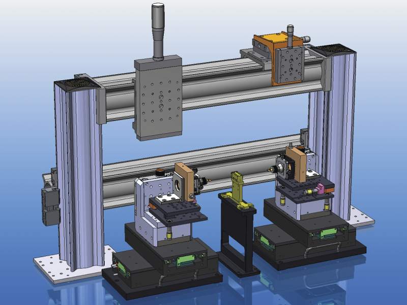
3-Station System
This dual 6-axis station (4 axes automated) with the middle station for loading and unloading stage of device is designed for single and multimode applications. It includes the following standard products.
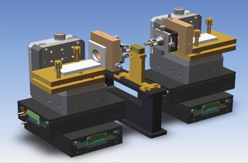
Fiber-to-Waveguide with Bridge
This optical fiber to waveguide alignment system features dual 6-axis motion systems (4 axes automated) for R&D applications. It includes the following standard products.
Automated Alignment for Production
For alignment of optical fibers or optical devices (single or multi-mode, single to multi-channel, Si photonics) it is critical that motion is controlled not just in X, Y, and Z but also in tip and tilt. When coupled with alignment software such as APOGEE, a hexapod becomes a turnkey automated alignment system.
In addition to hardware solutions, MKS has also developed algorithms that will make it easier to optimize and speed up fiber alignment. In our XPS-D motion controller, 7 alignment algorithms in the form of Application Programming Interface (API) are available in the firmware. When programming the fiber alignment system, any of these API functions can be used via a simple command to execute a motion pattern. For more details, check out our Optical Fiber Alignment technical note.
| Photonic Device Search Algorithm (PDSA) API | Beam Profile: Gaussian or Single Peak | Beam Profile: Plateau or Multiple Peaks | Find First Light | Find Peak Power | Find Peak Power along Beam Axis (Z) | Stop when Threshold Reached | Max Number of Axes |
|---|---|---|---|---|---|---|---|
| Axis by Axis | x | x | 6 | ||||
| Dichotomy | x | x | 6 | ||||
| Escalade (Continuous) | x | x | 3 | ||||
| Escalade (Square) | x | x | x | 3 | |||
| Raster | x | x | x | x | 2 | ||
| Spiral (Continuous) | x | x | x | 2 | |||
| Spiral (Square) | x | x | x | 2 |
Related Topics
Laser Diodes
Optical Fiber Alignment
- Fiber Optic Physics
- Optical Fiber Alignment
- Recommended Products for Fiber Alignment
- Software Supports Multiple Optical Fiber Alignment Options
Optical Receivers

For additional insights into photonics topics like this, download our free MKS Instruments Handbook: Principles & Applications in Photonics Technologies
Request a Handbook