
Non-Bridging Post Clamps
Non-Bridging Post Clamps
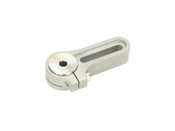
The Non-Bridging Post Clamps eliminate localized deformation of the optical table or breadboard as a result of full contact with the underlying mounting surface along the entire length. They greatly reduce the potential optical pitch/yaw misalignment introduced due to torque effects on the slot clamping mechanism and are recommended for the most demanding applications.
- Non-bridging design minimizes local deformation at clamping site
- Full 360° rotation of post and clamp prior to locking
- Flexure clamping for maximized stability
- Symmetric top and bottom design for left- and right-handed orientations
- Long and short length slots and magnetic base swivel versions
- Stainless steel construction See All Features


Test Data
Table Deformation
Purpose:
Simulations were performed to compare the deformation caused by an industry-standard clamping fork vs. the non-bridging clamping fork and to estimate if permanent deformation to the table would occur or not.
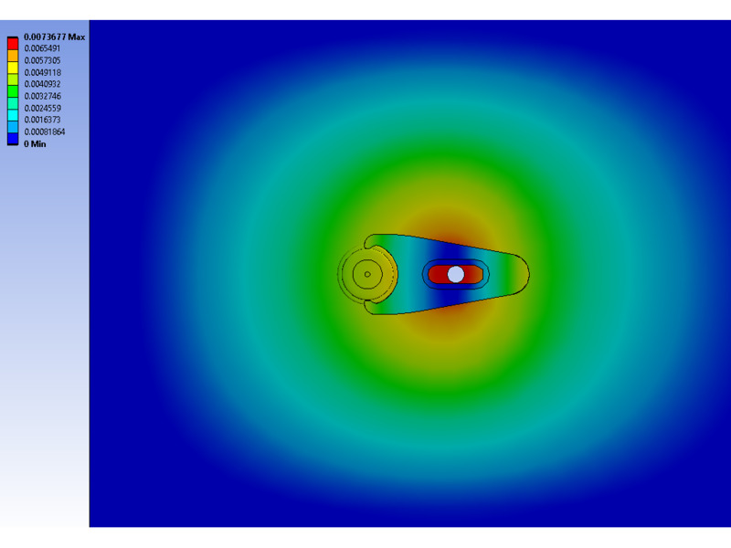
Results:
With a standard clamping fork (left), the table deforms at a maximum of .0074 in. when torqued to a maximum of 75 in-lb. In the areas surrounding the fork, deflections are much less. Under static conditions, the von mises stresses around the clamp exceed the table’s yield strength by less than 10%, thus small permanent deformation around it can occur.
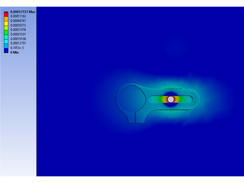
With a non-briding clamping fork (right), the table deforms at a maximum of .00058 in. when torqued to a maximum of 75 in-lb. In comparison to the industry standard, the deflections are greatly reduced. Under static conditions, the von mises stresses around the clamp are far less than the table’s yield strength resulting in significant margins of safety for yield and ultimate strength, thus any permanent deformation is unlikely.
Flexure Clamp Holding Torque
Purpose:
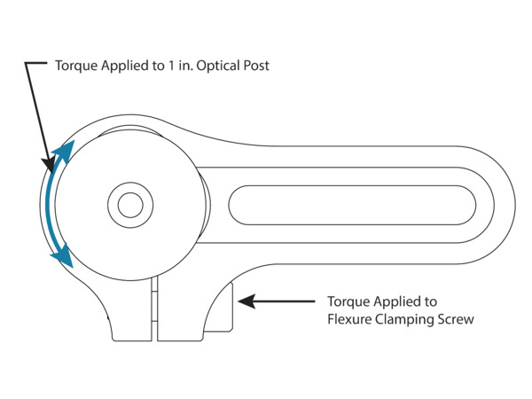
This test was performed to determine the ideal clamping torque applied to the flexure that is necessary to securely mount a 1 in. optical post within the bore of a non-bridging clamping fork.
Method:
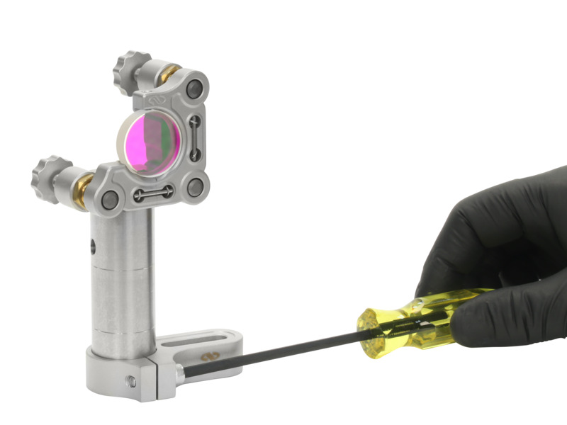
NBC-1 was used in this test and first mounted to an optical table. The flexure clamping cap screw was tightened by a torque wrench to specific torque values. An increasing rotational torque was applied to the optical post until it moved within the clamping arm's bore. The torque value right before it moved was recorded as holding torque.
Results:
To securely hold a 1 in. optical post, the flexure clamping screw should be tightened with 20-30 in-lb of torque for optimal performance.
Mounting Slot Holding Torque
Purpose:
This test was performed to determine the ideal mounting torque applied to the cap screw in the slot that is necessary to securely mount the clamping fork to the optical table. The mounting screw was installed in different positions within the slot to see if the recommended torque would vary.
Method:
The non-bridging clamping fork was mounted to an optical table by a cap screw in the slot. Three locations were tested: close to the post, in the middle of the slot, and far from the post. The cap screw was tightened by a torque wrench to specific torque values. Three locations An increasing rotational torque was applied to the clamping fork until it moved on the table. The torque value right before it moved was recorded as holding torque.
Results:
To securely mount the clamping fork to the optical table, the mounting screw in the slot should be tightened with 40-60 in-lb of torque for optimal performance.

Features
Non-Bridging Design
Non-Bridging Post Clamps are in full contact with the underlying optical table or breadboard along their entire length, eliminating any localized deformation of the clamp, optical table or breadboard when tightening the mounting screw. Non-bridging clamps therefore greatly reduce any potential optical pitch/yaw misalignment introduced due to torque effects on the slot clamping mechanism.
360° Rotational Freedom
Prior to clamping, the Non-Bridging Post Clamps and Non-Bridging Swivel Clamps can be fully rotated 360° to allow for quickly positioning of the optical assembly and then alignment of the slot to the closest or most convenient threaded hole in the optical table or breadboard.
Flexure Clamp
Once the post and clamp are aligned, the Non-Bridging Post Clamps are secured to the post with a flexure clamp that holds the post in position, clamping on three sections of the post circumference.
Magnetic Base Swivel Clamp
Non-Bridging Swivel Clamp utilizes a ring magnet for stable, initial positioning and a swivel clamp for flexibility in aligning to the optical table or breadboard. The NBSC-1 ring magnet is integrated into a pedestal base that includes a counterbored clearance hole for ¼-20 or M6 screws.


