Minimizing Drift

This tutorial is intended to serve as a checklist for building patch clamp workstations to achieve maximum stability and also as a list of possible remedies for an existing station with drift problems.

Drift is unwanted relative motion occurring between two points in the apparatus. For example, drift can arise between preparation and electrode, between electrode and amplifier headstage, or between electrode and microscope.

Motion appears in two ways: 1) as slow changes in position over a long period of time (the life of the experiment), and 2) short term changes, usually observed as oscillatory motion occurring at frequencies of 1 to 100 per second.

Causes and Sources of Drift

Temperature changes, either external or internal to the apparatus, can cause drift due to expansion and contraction of the materials used in construction. Sources are: changes in room temperature, the location of the researcher (warm breath, touch, radiated body heat), light sources such as microscope illuminator lamps and spot illuminators, nearby heat sources such as ovens, refrigeration units, power supplies, or electronic instrumentation which may cause localized temperature gradients.

Materials that creep or flow under stress, especially polymers such as nylon, polyurethane, and Teflon. Changes in local stress within many thermoplastic components will gradually be relieved by strain (movement) within the material. This type of material is often used in amplifier headstages for holding recording electrodes and is a common cause of drift observed in patch clamp setups.

Use of high viscosity lubricants in bearings and leadscrews of positioning systems is a common method used by manufacturers to "tighten" low precision components. However, after adjustments are made during operation, the relatively thick film of lubricant in gaps will slowly flow under pressure causing the component to drift.

Vibrations can be induced in the apparatus by a number of sources both internal and external.

Floor motion is probably the most significant contributor. Sources of building vibration can come from elevators, ventilation machinery, air conditioners, foot traffic and closing doors. Placing the apparatus on isolated platforms rather than rigid tables or benches can reduce motion by up to 100 times depending on the vibration frequency. There are several suppliers of vibration isolation tables especially designed for this purpose.

Often airborne pressure disturbances can induce vibration. Acoustic noise produced by pumps and other motorized equipment can induce motion in sensitive equipment. Low frequency (10 Hz and lower) room pressure variations can be transmitted from air conditioning equipment via the ventilation ducting entering the room.

Electrical wiring, cabling, tubing, and ducting leading to and from the apparatus can induce motion.

Fans, blowers, pumps, actuator motors and other components that are integral parts of the workstation may produce vibrations during operation.

For more information, please also see our tutorial on Controlling Laboratory Vibrations.

Hints For Improving Stability And Component Selection Considerations

When laying out the design of the station keep the center of gravity low and close to the table surface. Make the base dimensions large compared to the height of the center of gravity.

Patch clamp workstations usually consists of a number of components: microscope, micromanipulators, amplifier, and specimen chambers together with accessory components for thermal control, imaging, and drug perfusion. All of these components must be physically integrated and anchored on a stable and rigid supporting surface. A structural "loop" is formed consisting of all the components connecting the electrode to the specimen. A typical loop may consist of microscope stage, focusing mechanism, microscope body and base, micromanipulator, amplifier headstage and electrode holder. In order to remain stable relative to the microscope, each component in the mechanical structure connecting the electrode to the specimen must be stable as well as the interconnections between the components.

When designing structural support members:

1. Keep the structural loop short and with as few connections as possible.

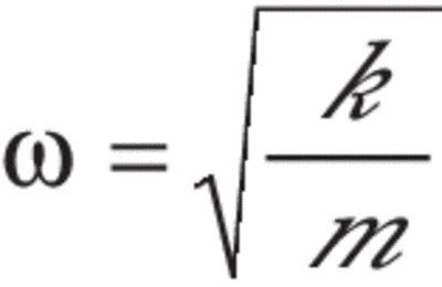
2. Use materials with a high stiffness to weight ratio. Design components with high stiffness and low mass. Use lightening holes to remove material from structural parts that are not under stress. A common erroneous assumption made in designing structures that support lightweight components is that heavy, massive structural components are better than lighter components. This is not true if a structure is to be resistant to vibration. To be resistant to vibration a structure must have a high natural frequency and possess internal damping (energy loss mechanism). The natural frequency of a mass supported by a spring is determined by the following relationship:

Where:

Spring equation

ω = Natural frequency of the structure

κ = Stiffness of the structure

m = Mass of the structure

3. Use materials with low expansion coefficients. Ceramics are better than plastics. Avoid mating structural components with materials having large differences in expansion coefficients to prevent "bimetallic effect" internal stress buildup.

4. In general, use aluminum where the ambient temperature is stable. If large temperature changes are expected, use steel, which has about two-thirds the expansion of aluminum. Avoid using materials such as nylon, Teflon and polyurethane that creep or flow under stress in structural components that are subject to varying loads such as clamps, slides, or brackets.

5. Use high quality precision positioning components with dry film lubricants or those assembled with sparing use of low viscosity lubricants in critical bearing surfaces. Many of these components are available from manufacturers of positioning equipment for laser/optics research.

Rotating components that must be placed on the apparatus should be balanced and/or mounted with vibration isolation mounts to minimize the coupled forces.

6. Wiring, tubing, ducting, cabling runs should be strain relieved at a solid attachment point on the table frame or floor. Generous service loops should be placed in the runs so that no forces can be transmitted along the run axis to the apparatus

Allow time for apparatus to thermally equilibrate after power up (typically 1 hour but may require as much as several hours in extreme cases).

Tighten room temperature control. A 20-cm long metal structure can change its length by as much as 5 microns for a temperature change of only 1-degree Fahrenheit.

Enclose the apparatus to thermally isolate it from radiant heat sources and air currents.

Have the operator stay as far away from recording site as possible.

Place a sensitive thermometer near the apparatus to monitor changes in temperature.

Where possible, place illuminator lamps away from the apparatus or use fiber optic bundles to pipe in light for spot illumination.

Remove rubber feet from the base. Clamp the microscope base to the table using a solid three-point support design.

Place specimen holder on a separate structure mounted directly on the platform. This shortens the structural loop.

Avoid using plastics to electrically isolate the amplifier headstage. Use ceramic materials or metal where possible.

Use remote control micromanipulators such as motorized or hydraulic systems to eliminate hand induced motions and transfer of body heat.

The better optical table tops are internally damped metal composite structures with a thickness of at least 2 inches. Thicker tops have larger mass for better vibration isolation when placed on isolators, but if too thick the operator’s legs will not fit comfortably beneath the table. These tops can be purchased with standard or custom mounting hole patterns for attaching components.

Vibration isolators work by attenuating motion (displacement, velocity, and acceleration). If a mass is supported by a spring resting on a moving floor, all frequency components of floor motion above a certain frequency will be attenuated and will not reach the supported mass. This critical frequency is determined by the following relationship:

Where:

Spring equation

ω = Natural frequency of the structure

κ = Stiffness of the structure

m = Mass of the structure

Therefore, for best isolation the resonant frequency should be as low as possible (large relative motion between the supported load and the floor). That is, the mass should be large, and the spring should be soft, just the opposite of the goals desired when designing the workstation structure.

Pneumatic isolators provide the best vibration isolation, however, they are soft and shifting loads or placing of operator’s hands or arms will tilt the station. To minimize such motions, utilize armrests attached to the support frame. The frame itself should be a rigid welded structure with adjustable feet to evenly distribute the load to all four legs. Built-in casters are a convenient accessory if the station must be moved.

Place the center of gravity of the heaviest component, usually the microscope, as low and as close to the center of the table as possible for best performance.