The Effect of Dispersion on Ultrashort Pulses

In the time domain, the electric field for a Gaussian pulse with a carrier frequency, ω0, pulse duration, Δt, and phase, θ(t), can be described by,

Equation 1

where c.c. denotes the complex conjugate. In this expression, At is the amplitude of the pulse, ω0 determines the color of the pulse, Δt determines the minimum pulse duration and consequently the bandwidth of the pulse, and θ(t) determines the temporal relationship among the frequency components contained within the bandwidth of the pulse. θ(t) plays an important role in altering the pulse duration. It is the term that is responsible for pulse broadening in dispersive media and can be thought of as adding a complex width to the Gaussian envelope.

The description of the Gaussian pulse given by (1) is intuitive in the sense that it is fairly straightforward to conceptualize a pulse in the time domain. However, when dealing with pulses traveling through dispersive media, it can be problematic to work in the time domain. For example, in order to determine the duration of a pulse after traveling through some dispersive material, it is necessary to solve a convolution integral1 which in general must be done numerically. However, due to the fact that convolutions become products upon a Fourier transformation2, it is convenient to solve this type of problem in the frequency domain.

Time and frequency along with position and momentum represent a class of variables known as Fourier pairs2. Fourier pairs are quantities that can be interconnected through the Fourier transform. Performing a Fourier transform on equation (1) yields,

Equation 2

(for the sake of brevity, negative frequency components are omitted). The electric field is now expressed as a function of frequency, Δω and Δt are related through the uncertainty relation1

ΔωΔt=4ln(2),

and the spectral phase, φ(ω), describes the relationship between the frequency components of the pulse. In equation (2), ω as well as Δω represent angular frequencies. Angular frequency can be converted to linear frequency, ν (i.e. the observable quantity), by dividing it by 2 π,

ν = ω/2 π

In terms of the linear frequency, the uncertainty principle is given by,

cB = ΔνΔτ = 2ln(2)/ π

When an input pulse, Ein(ω), passes through a dispersive medium, the phase added by the material is given simply by the product of the input field with the transfer function of the material. The emerging pulse Eout(ω), is given by,

Equation 3

where φMat(ω - ω0) is the spectral phase added by the material and R(ω) is an amplitude scaling factor which for a linear transparent medium can be approximated by, R(ω) ≈ 11.

It is a common convention to express spectral phase as a Taylor expansion around the carrier frequency of the pulse as shown below,

Equation 4

This approach allows a more straightforward understanding of the effect of material dispersion on properties of the pulse. Taking into account that

φ(ω) = k(ω)L,

where k is the propagation constant, and L is the length of the medium, while also considering that the group velocity is defined as

νG = dω/dk,

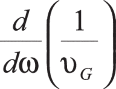
it is easy to see that first term in (4) adds a constant to the phase. The second term, proportional to 1/νG, adds delay to the pulse. Neither of these terms affects the shape of the pulse. The third term, referred to as group delay dispersion (GDD), is proportional to

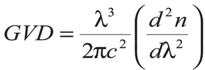
also known as group velocity dispersion (GVD). It introduces a frequency dependent delay of the different spectral components of the pulse, thus temporally changing it. The GDD and GVD are related through

φ2(ω) = k2(ω)L

The fourth term, referred to as Third Order Dispersion (TOD) applies quadratic phase across the pulse. For the purpose of this tutorial, we will truncate the series at the third term, GDD, only making references to higher order terms when necessary. Truncating equation (4) at the third term allows us to rewrite equation (3) for a Gaussian pulse as,

Equation 5

hence phases in the frequency domain are simply additive. This result underscores the advantage of performing these types of calculations in the frequency domain.

To arrive at the new pulse duration, it is necessary to transform the spectral envelope of equation (5) back into the time domain. Performing this Fourier transform, the pulse envelope is given by,

Equation 6

where φ2 is the sum of the group delay dispersion of the material and the group delay of the pulse. In order to get the new pulse duration, Δtout, it is necessary to obtain the intensity, Iout(t), by squaring the electric field in equation (6) and then relating Iout(t) to the general form for a Gaussian pulse,

Equation 7

Solving equation (7) for Δtout,

Equation 8

provides an expression for the pulse duration. Finally, by solving equation (8) for group delay dispersion while replacing the transform limited pulse duration with the spectral bandwidth of the pulse, GDD can be expressed completely in terms of observables (i.e. pulse width and spectrum),

Equation 9

where Δν = cΔλ/λ2. In general, cB is a function of the pulse profile as shown in Table 1. It should be noted that equation (9) is strictly for Gaussian pulses.

Field Profile Gaussian Sech Lorentzian Rectangle
CB 0.441 0.315 0.142 0.443

Table 1: Time-bandwidth product CB for various pulse profiles

Dispersion in materials is defined by the group velocity dispersion. In order to estimate amount of GDD introduced by a material of length L, one has to calculate the wavelength dependent index of refraction, n(λ), typically in the form of a Sellmeier’s type equation, and then calculate second derivative at the wavelength of interest. GVD is related to the second derivative of refractive index with respect to wavelength by

GDD is simply a product of GVD with the length of the material. The dispersive properties of several optical materials are shown in Table 2.

TOD is the frequency dependence on the GVD. The dispersion properties are specified in units of fs3. TOD of several optical materials are shown in the Table below.

Table 2: Material parameters for fused silica, LakL21, SF10 and BK7 glass

Material Λ
(nm)
n
(λ)
dn/dΛ
(µm-2)
d2n/dΛ2
(µm-2)
d3n/dΛ3
(µm-3)
GVD
(fs2/mm)
TOD
(fs3/mm)
Fused Silica 400 1.470 -0.109 0.861 -9.600 97.57 30.26
Fused Silica 450 1.466 -0.076 0.512 -4.984 82.55 27.30
Fused Silica 500 1.462 -0.055 0.323 -2.809 71.50 25.59
Fused Silica 550 1.460 -0.042 0.214 -1.686 62.91 24.67
Fused Silica 600 1.458 -0.033 0.146 -1.064 55.93 24.33
Fused Silica 650 1.457 -0.027 0.103 -0.699 50.05 24.48
Fused Silica 700 1.455 -0.023 0.074 -0.476 44.93 25.04
Fused Silica 750 1.454 -0.020 0.054 -0.333 40.36 26.06
Fused Silica 800 1.453 -0.017 0.040 -0.239 36.16 27.47
Fused Silica 850 1.452 -0.016 0.030 -0.175 32.23 29.45
N-LakL21 400 1.659 -0.179 1.470 -16.950 166.54 57.03
N-LakL21 450 1.652 -0.123 0.860 -8.552 138.85 49.25
N-LakL21 500 1.647 -0.089 0.539 -4.731 119.24 44.65
N-LakL21 550 1.643 -0.067 0.355 -2.804 104.45 41.87
N-LakL21 600 1.640 -0.052 0.233 -1.753 92.74 40.29
N-LakL21 650 1.638 -0.042 0.171 -1.144 83.12 39.56
N-LakL21 700 1.636 -0.035 0.123 -0.774 74.94 39.55
N-LakL21 750 1.634 -0.029 0.091 -0.540 67.80 40.17
N-LakL21 800 1.633 -0.025 0.068 -0.386 61.40 41.42
N-LakL21 850 1.632 -0.022 0.051 -0.282 55.55 43.27
N-SF10 400 1.778 -0.543 6.100 -102.657 691.28 547.87
N-SF10 450 1.757 -0.335 2.930 -37.779 472.88 316.47
N-SF10 500 1.743 -0.225 1.636 -17.338 362.19 220.92
N-SF10 550 1.734 -0.161 1.003 -9.111 295.42 172.28
N-SF10 600 1.727 -0.120 0.655 -5.246 250.48 144.17
N-SF10 650 1.722 -0.093 0.448 -3.229 217.8 126.60
N-SF10 700 1.717 -0.074 0.318 -2.090 192.92 115.11
N-SF10 750 1.714 -0.060 0.232 -1.408 172.99 107.49
N-SF10 800 1.711 -0.050 0.173 -0.980 156.52 102.52
N-SF10 850 1.709 -0.042 0.131 -0.701 142.55 99.53
N-BK7 400 1.531 -0.133 1.079 -12.314 122.04 40.79
N-BK7 450 1.525 -0.092 0.633 -6.271 102.12 35.60
N-BK7 500 1.521 -0.066 0.397 -3.492 87.89 32.59
N-BK7 550 1.519 -0.050 0.262 -2.078 77.04 30.84
N-BK7 600 1.516 -0.040 0.179 -1.304 68.38 29.95
N-BK7 650 1.515 -0.032 0.126 -0.853 61.19 29.70
N-BK7 700 1.513 -0.027 0.091 -0.578 55.02 29.99
N-BK7 750 1.512 -0.023 0.066 -0.403 49.58 30.79
N-BK7 800 1.511 -0.020 0.049 -0.289 44.65 32.10
N-BK7 850 1.510 -0.018 0.037 -0.211 40.09 33.92

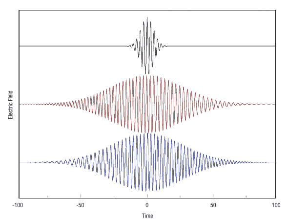
By measuring the spectrum and autocorrelation for a Gaussian pulse, equation (9) can be used to determine the amount of GDD. Figure 1 illustrates the results of a numerical simulation of the electric field for three pulses, all containing 100 nanometers of bandwidth, centered around 800 nanometers. The black curve corresponds to a pulse with the GDD set to zero, the red curve corresponds to a pulse with the GDD set to 5 fs2 and the blue curve corresponds to a pulse with the GDD set to -5 fs2. The pulse with the minimum time duration corresponds to the pulse having zero GDD. For the red pulse (positive chirp), the higher frequency components are lagging behind the lower ones and for the blue pulse (negative chirp), the lower frequency components are lagging behind the higher ones.

The effect of GDD on pulse with 100 nm bandwidth
Figure 1. The effect of GDD on pulse with 100 nm bandwidth.

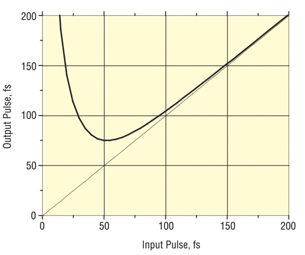
Figure 2 shows the width of a Gaussian pulse at 800nm before and after propagation through 20 mm of BK7 glass calculated using equation (8) and data from Table 2.

Broadening of a femtosecond pulse at 800 nm after propagation through 20 mm of BK7
Figure 2. Broadening of a femtosecond pulse at 800 nm after propagation through 20 mm of BK7.

The amount of introduced GDD in this case is about 1000 fs2, and is equivalent to propagating the beam through only a few optical components. It is clear that the effect is not significant for pulses longer than 100 fs. However, a 25 fs pulse broadens by a factor of 4.

References

  1. J. Diels and W. Rudolf, Ultrashort Laser Pulse Phenomena, Second Edition (Massachusetts, Academic Press, 2006).
  2. E. Oran Brigham, The Fast Fourier Transform: An Introduction to Its Theory and Application (New Jersey, Prentice Hall, 1973).
  3. To learn about dispersion compensation using a prism compressor, see Newport's Application Note 29