The electric field of a light wave vibrates perpendicularly to the direction of propagation as shown in Figure 1. Since the electric field is a vector quantity, it can be represented by an arrow that has both a magnitude (or length) and a direction of orientation. This orientation direction is the polarization of the light. There are basically three polarization states: linear, circular, and elliptical. These terms describe the path traced out by the tip of the electric field vector as it propagates in space. Figure 1 shows a snapshot in time of a linearly polarized wave. Although the electric field alternates direction (or sign), it stays confined to a single plane. Therefore, sitting at a fixed point in z as time passes, the arrow tip would oscillate up and down along a line. The angle (θ) of this line with respect to some reference set of axes completely specifies this linear polarization state. For circular polarization, the electric field vector tip forms a helix or corkscrew shape. For a fixed point in z, the vector would rotate in time, like the second hand on a watch. Circularly polarized light can be either left-handed or right-handed, depending on the clockwise or counterclockwise nature of the rotation. Elliptical polarization is the most general case of polarization. It is the same as circular polarization but with unequal major and minor axes (for circular polarization, these are equal).
Incoherent light sources such as lamps, LEDs, or the sun typically emit unpolarized light, which is a random superposition of all possible polarization states. On the other hand, the output light from a laser is typically highly polarized, that is, it consists almost entirely of one linear polarization. Analyzing laser polarization is easier if it is decomposed into two linear components in orthogonal directions. In this way, depicting the polarization can be done using the standard symbols shown in Figure 1. The upper part of the table lists the symbols generally used for unpolarized, vertically polarized, and horizontally polarized light. For the graphic shown in the figure, the vertical direction would be along the y-axis while the horizontal direction would lie along the x-axis. When a plane of incidence is specified (see lower part of table in Figure 1), the polarization components acquire specific designations. S-polarization refers to the component perpendicular to the plane while P-polarization refers to the component in the plane. Examples of the depictions of linearly polarized light are illustrated in the remaining figures of the section.
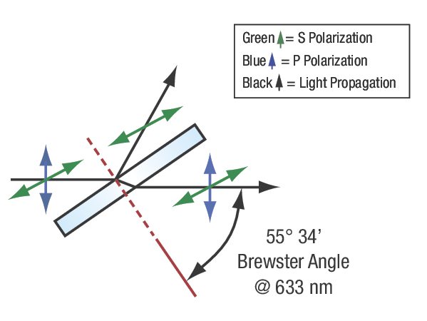
The way in which polarized light interacts with an optical material can enable selective filtering of the polarization or conversion of the incident polarization state to a different one. This polarization control relies on a material's optical properties to respond differently depending on the polarization of the incident light. A material that exhibits birefringence, or different refractive indices for different input polarizations, is said to be anisotropic. This anisotropy affects the transmission and absorption properties of light and is the primary mechanism used in polarizers and waveplates as discussed below. However, even isotropic materials (same index for different polarizations) can enable polarization selection via reflection. The Fresnel equations describe the change in reflectivity as a function of angle of incidence. For a linearly polarized beam, both S- and P-polarizations exhibit different changes in reflectivity versus incident angle. There is an incident angle known as Brewster's angle (θB) at which P-polarized light is transmitted without loss, or exhibits zero reflectance, while S-polarized light is partially reflected. This angle can be determined from Snell's law to be θB = arctan(n2/n1). Figure 2 shows this response when light is incident from air onto a dielectric material where θB ≈ 56°. This polarization-selective reflectivity is exploited in laser cavities to produce strongly polarized light and for fine tuning of the output laser wavelength.
 Over 8,000 products in-stock! & FREE 2-Day shipping on all web orders!* Learn More FREE T-Shirt with orders $250+ Details
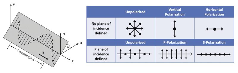

 Ultra-High Velocity