Polarization Control with Optics
Precise control of polarization behavior is necessary to obtain optimal performance from optical components and systems. Characteristics such as reflectivity, insertion loss, and beamsplitter ratios will be different for different polarizations. Polarization is also important because it can be used to transmit signals and make sensitive measurements. Even though the light intensity may be constant, valuable information can be conveyed in the polarization state of an optical beam. Deciphering its polarization can reveal how the beam has been modified by numerous material interactions (magnetic, chemical, mechanical, etc.). Sensors and measurement equipment can be designed to operate on such polarization changes. For these reasons, optical components capable of filtering, modifying, and characterizing a light source's polarization are valuable. Such polarization control can be accomplished by exploiting the reflection, absorption, and transmission properties of materials used in these components. The physical phenomena that enable polarization control, as well as the key components that exploit them, are discussed below.
Polarization
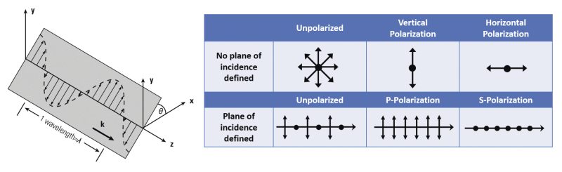
The electric field of a light wave vibrates perpendicularly to the direction of propagation as shown in Figure 1. Since the electric field is a vector quantity, it can be represented by an arrow that has both a magnitude (or length) and a direction of orientation. This orientation direction is the polarization of the light. There are basically three polarization states: linear, circular, and elliptical. These terms describe the path traced out by the tip of the electric field vector as it propagates in space. Figure 1 shows a snapshot in time of a linearly polarized wave. Although the electric field alternates direction (or sign), it stays confined to a single plane. Therefore, sitting at a fixed point in z as time passes, the arrow tip would oscillate up and down along a line. The angle (θ) of this line with respect to some reference set of axes completely specifies this linear polarization state. For circular polarization, the electric field vector tip forms a helix or corkscrew shape. For a fixed point in z, the vector would rotate in time, like the second hand on a watch. Circularly polarized light can be either left-handed or right-handed, depending on the clockwise or counterclockwise nature of the rotation. Elliptical polarization is the most general case of polarization. It is the same as circular polarization but with unequal major and minor axes (for circular polarization, these are equal).
Incoherent light sources such as lamps, LEDs, or the sun typically emit unpolarized light, which is a random superposition of all possible polarization states. On the other hand, the output light from a laser is typically highly polarized, that is, it consists almost entirely of one linear polarization. Analyzing laser polarization is easier if it is decomposed into two linear components in orthogonal directions. In this way, depicting the polarization can be done using the standard symbols shown in Figure 1. The upper part of the table lists the symbols generally used for unpolarized, vertically polarized, and horizontally polarized light. For the graphic shown in the figure, the vertical direction would be along the y-axis while the horizontal direction would lie along the x-axis. When a plane of incidence is specified (see lower part of table in Figure 1), the polarization components acquire specific designations. S-polarization refers to the component perpendicular to the plane while P-polarization refers to the component in the plane. Examples of the depictions of linearly polarized light are illustrated in the remaining figures of the section.
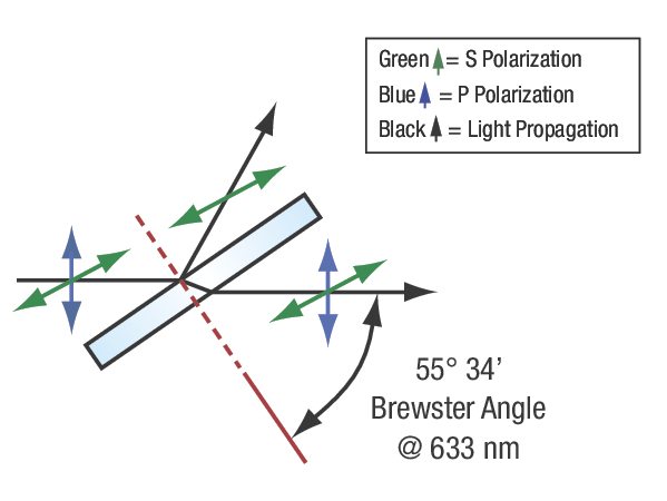
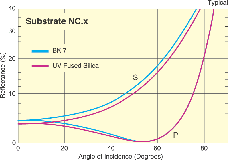
The way in which polarized light interacts with an optical material can enable selective filtering of the polarization or conversion of the incident polarization state to a different one. This polarization control relies on a material's optical properties to respond differently depending on the polarization of the incident light. A material that exhibits birefringence, or different refractive indices for different input polarizations, is said to be anisotropic. This anisotropy affects the transmission and absorption properties of light and is the primary mechanism used in polarizers and waveplates as discussed below. However, even isotropic materials (same index for different polarizations) can enable polarization selection via reflection. The Fresnel equations describe the change in reflectivity as a function of angle of incidence. For a linearly polarized beam, both S- and P-polarizations exhibit different changes in reflectivity versus incident angle. There is an incident angle known as Brewster's angle (θB) at which P-polarized light is transmitted without loss, or exhibits zero reflectance, while S-polarized light is partially reflected. This angle can be determined from Snell's law to be θB = arctan(n2/n1). Figure 2 shows this response when light is incident from air onto a dielectric material where θB ≈ 56°. This polarization-selective reflectivity is exploited in laser cavities to produce strongly polarized light and for fine tuning of the output laser wavelength.
Polarizers and Waveplates
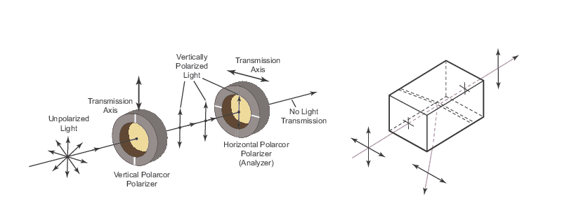
A polarizer is an optical component whose transmission depends strongly on the incident polarization of the light. Polarizers typically filter linear polarization, so an ideal polarizer would transmit 100% of one polarization component while rejecting all of the orthogonal component (see Figure 3). In practice, a portion of the undesired polarization will be transmitted. The transmittances of the target polarization and the undesired polarization through the polarizer are measured (by simply rotating the polarizer by 90 degrees) and the extinction ratio is defined as the ratio of these transmittances. The difference between a polarizer and a Brewster plate is that the former results in strong polarization-dependent transmission while the latter does not (only the reflection is highly polarized).
Polarizers rely on birefringent materials and, since the index of refraction is complex, these materials can exhibit a polarization-dependent absorption and refraction. The first polarizers were based on selective absorption of incident light and are usually denoted as dichroic polarizers. Typical materials used for this anisotropic absorption are stretched polymers or elongated silver crystals; their operation is shown in Figure 3. The strongly absorbing axis of the material is placed perpendicular to the desired output polarization such that the undesired polarization is strongly absorbed. A different type of polarizer is based on the anisotropic refractive indices of a birefringent crystal such as calcite. A birefringent crystal will produce an o-wave or e-wave depending on the axis of the crystal to which the polarization component is aligned. These waves experience different refractive indices and will possess different critical angles for TIR, resulting in one polarization component being reflected while the other is transmitted (see Figure 3). By placing two calcite prisms back-to-back to form a rectangular optic, the transmitted beam will follow the same direction as the incident beam. The gap between these prisms can either be air or an optically transparent cement, depending on whether a high damage threshold or large acceptance angle, respectively, is desired.
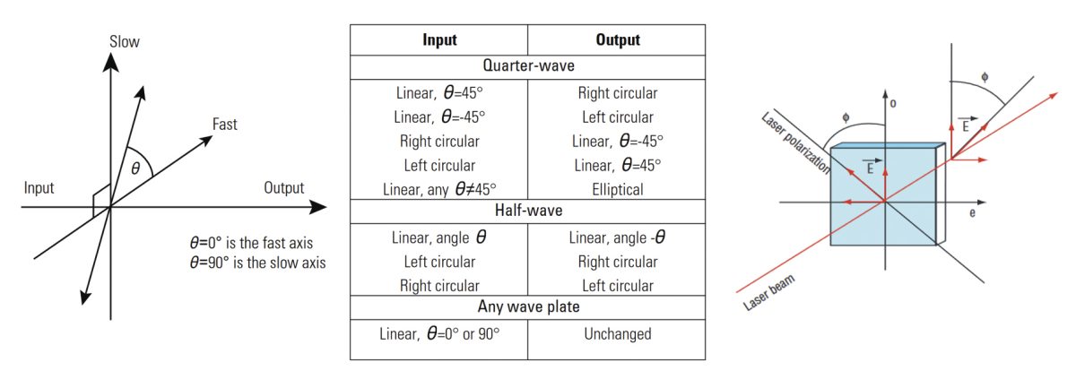
Polarizers are used to filter the input polarization, increase its purity, or separate orthogonal components of a linearly polarized beam. However, a polarizer cannot convert the polarization state of the input light into a different polarization state. For this type of modification, an optical component known as a waveplate or retarder is required. To understand its operation, it is important to know that any polarization state (not just linear) can be decomposed into orthogonal components. The difference between the polarization states then results from the phase difference between the orthogonal components. Linear polarization possesses components that are in-phase, i.e., no phase difference, but have different amplitudes depending on their angle. Circular and elliptical polarization components possess a phase difference of π/2 or a quarter of a wavelength (circular polarization has the same amplitudes for the different components while elliptical has different amplitudes). Consequently, in order to convert one polarization to another, the phase difference between the two components must be controlled. This can be accomplished by sending a polarized beam into a birefringent crystal such that the o-wave or e-wave each experience a different phase delay. The operation of a waveplate and a summary of how quarter and half waveplates convert one polarization state to another are shown in Figure 4. An important case of polarization conversion is shown on the right side of Figure 4. A half waveplate can rotate the angle of a linearly polarized beam to any other angle, which can be used for rotating a vertically polarized laser beam to obtain horizontal polarization. Furthermore, proper combinations of waveplates and polarizers can be used to form optical systems that allow for variable attenuation of a laser beam or for isolating a laser cavity from spurious reflections.

For additional insights into photonics topics like this, download our free MKS Instruments Handbook: Principles & Applications in Photonics Technologies
Request a Handbook