Sorry, this family of products is no longer available.

Fiber-Coupled 25 Gbit VCSEL Laser Source
Fiber-Coupled 25 Gbit VCSEL Laser Source
Designed for test and measurement of 25-Gbit/s datacom devices, the Model 1784 is an 850 nm, 25-Gbit/s, directly modulated, multimode vertical-cavity surface-emitting laser (VCSEL).
- Ideal source for testing 25 Gbit/s datacom devices
- 50 µm fiber output for convenient and easy use
- Small package size See All Features
Specifications
- Center Wavelength850 nm
- Bit Rate25 Gbit/s
- Output Power0.75 mW
- Bandwidth, Small Signal18 GHz
- Noise/Ripple (rms)< 2.8 %
- Fiber Type50 mm multimode
- Fiber-Optic ConnectorFC/PC
- Cut-off Frequency10 MHz
- Power Requirements+/-15 V, 50 mA
- Operating Temperature Range10 to 30 :deg;C
- Storage Temperature Range-20 to 30 :deg;C
Features
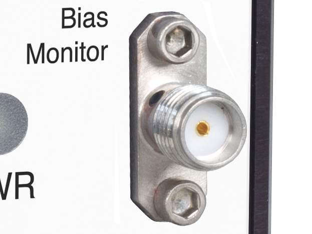
AC-coupled input and internal bias circuitry
For desired optical power levels, the bias point and input signal voltage swing can be determined. The bias point is set on the front panel of the Model 1784, and the input voltage swing should be set to give the desired optical power swing. This allows connection to any high-speed 50 Ω SMA compatible signal source without the need for additional bias circuitry.
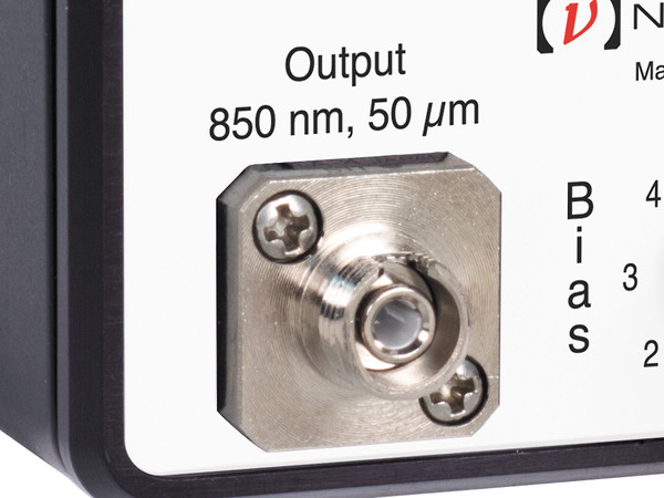
Utilizes a 50 µm output fiber connection
The VCSEL output is coupled into the internal 50 µm core multimode fiber with a somewhat defocused GRIN lens. This enables Class I laser operation, and also reduces noise in the presence of optical feedback. The coupling also results in excitation of cladding modes which are not stripped internally, so an external mandrel–wrap is advised if cladding modes are unacceptable. You can use either 50 µm or 62.5 µm fiber with the device.
Typical Eye Diagrams
Eye diagrams are a good measure of system performance. The quality of the eye diagram will show if your source has good timing, power levels, proper synchronization, and long-term reliability. If the opening of the eye is larger it gives better certainty that, when the data is sampled, it is a 1 (top of the eye diagram) or a 0 (bottom of the eye diagram). We repeatedly sampled our VCSEL over a period of time at various speeds to obtain the eye diagrams shown above. By pairing Model 1784 VCSEL with Model 1484-A-50 photoreceiver, you can create your own baseline eye diagrams. With that baseline you can insert an optical component between the VCSEL and photoreceiver to test how they would affect data transmission.
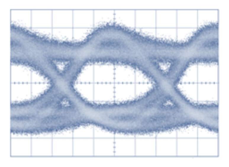
20 Gbps
High-performance microwave circuitry
The laser is housed in a high–performance microwave housing to minimize distortion of input signals. A bias current is supplied internally, and the high-speed input is connected to a 50-ohm transmission line which is AC coupled to the laser. The VCSEL output is coupled into a 0.1 m, 50 µm core graded–index fiber via a GRIN lens, and internally connected to a front panel FC connector. This ensures clean delivery of the electrical input to the VCSEL chip.
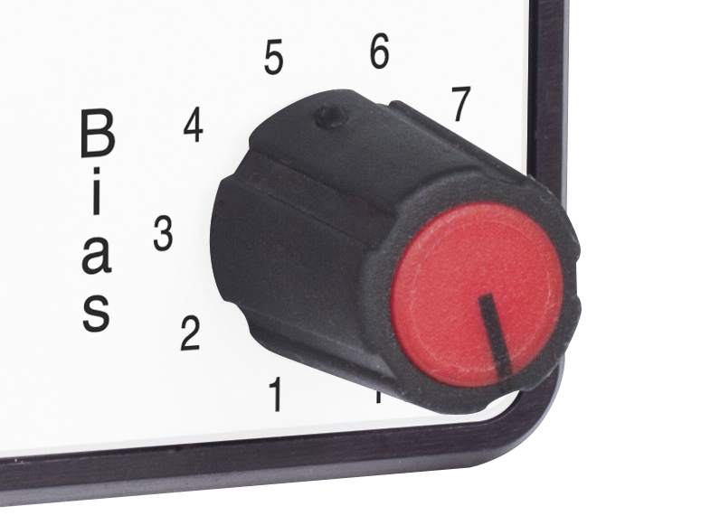
Allows for optimization of the VCSEL bias for different datacom applications.
Resources
Literature
1784 VCSEL Datasheet(761.7 kB, PDF)
Manuals
1784 VCSEL Fiber-Coupled Laser Source Manual(2.7 MB, PDF)