Flow Cytometry
Flow cytometry is an analytical technique that can rapidly measure the properties of individual cells or particles as they pass through a beam of light, typically a laser. A flow cytometer takes a sample of cells, transitions them into a single stream and uses lasers and/or light sources to excite biomarkers or labels on the cells to count the number of relevant constituents. The properties measured include relative particle size, relative granularity or internal complexity, and relative fluorescence intensity.
The method requires several photonics components, starting with lasers and other light sources with small, tightly focused beams that can illuminate a single size cell or particle (~30 µm diameter). Laser light with specific wavelengths is needed to excite labels or fluorophores on a cell. Dichroic filters with precision coatings are needed for narrow reflection/transmission bands and high optical density for out-of-band rejection. All photonics components must be precisely aligned and controlled with µm spatial resolution.
A flow cytometer (Figure 1) consists of the three major component systems. The first is the fluidics system that transports sample particles to the laser beam in a narrow, single particle wide stream. The second is the optical system composed of lasers or light sources that illuminate the particles in the sample stream as well as optical filters and beamsplitters that direct the post-sample light signals to optical detectors for counting and processing. The third system is the electronics and signal processing equipment that converts the detected optical signals to electronic signals for processing and analysis.

Flow Cytometry Systems
Fluidics System
The fluidics system creates a stream of single particles that can be interrogated individually by the instrument's detection system. The sample is focused by the Bernoulli effect (Figure 2), creating a stream of particles in single file using a method called hydrodynamic focusing. Under optimal conditions (laminar flow), there is no mixing of the central fluid stream and the sheath fluid.

Optics and Detection
Following hydrodynamic focusing, the particle stream passes through one or more focused laser beams and light scattering or fluorescence emission occurs. The optical output is collected as forward or side scattered light (FSC or SSC) by a PMT or photodiode and the optical data is used to characterize the cell properties. FSC data provides an estimate of a particle's size while SSC provides information on the relative internal complexity of a cell. By combining the FSC and SSC information with fluorescence labeling, it is possible to differentiate cell types in a heterogeneous population such as blood.
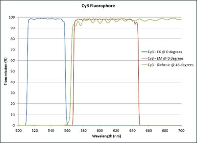
The detectors in most flow cytometers are usually PMTs. The specificity of detection is controlled by optical filters. There are three major filter types: long pass filters that transmit light above a cutoff wavelength; short pass filters that transmit light below a cutoff wavelength; and band pass filters that transmit light within a narrow band of wavelengths (see Optical Filter Characteristics for details). These are dichroic filters that block light by phased reflection, allowing only certain wavelengths of light to pass through while interfering with other wavelengths (Figure 3).

When placed at an angle to the oncoming light, a dichroic filter acts as a mirror, allowing it to perform two functions: transmitting specific wavelengths in the forward direction and reflecting the remaining light at a 90o angle. This allows the light path to be passed through a series of filters. The precise choice and order of the filters can be arranged so that multiple signals can be detected simultaneously (Figure 4).

Signal and Pulse Processing
Every time a particle passes through the interrogation point, a signal pulse is generated in every detector in Figure 4 with the current from each PMT proportional to the intensity of the scatter or fluorescence signal generated by the cell. These pulses can be mapped by plotting signal as a function of time.
Not all signals that are generated correspond to a particle of interest. PMTs are extremely sensitive and detect signals from irrelevant sources such as stray light, dust, very small particles and debris. The number of these irrelevant pulses can be orders-of-magnitude higher than the number of pulses that are generated by particles of interest. It is therefore desirable and necessary to set a threshold below which non-essential data are ignored. This is done by designating a trigger channel, usually a forward scatter detector, and setting a threshold signal intensity in that channel for recording scattering events. Any pulse that fails to exceed the threshold level is ignored in all detectors; any pulse that surpasses the threshold level is fully processed by the electronics.
The electronics process fluorescence signals for display, analysis, and interpretation. The analog current from the PMT is typically digitized and the pulse height, area, and width determined. The height and area, or maximum and integral, respectively, are used to measure signal intensity since their magnitudes are proportional to the number of photons that reach the PMT. The width of the pulse is proportional to the time that the particles spend in the laser and this can be used to distinguish between single particles or closely interacting particles and doublets.
Applications of Flow Cytometry
The ability to simultaneously measure multiple parameters on a cell-by-cell basis is the most powerful attribute of analytical flow cytometry, making it suitable for a wide range of applications. Most commonly, it is used to determine the presence of antigens either on the surface or within cells. In addition, flow cytometry may be used for the analysis of DNA or RNA content, and for functional studies on cells. The following broad range of technological activities employ flow cytometry analytical tools:
- Medicine
- Hematology
- Oncology
- Immunology
- Genetic testing
- Biochemistry and molecular biology, e.g., proteomics, glycomics
- Marine science
- Biosynthesis
- Cell health and biology (including stem cells)
- Screening
- Cell cycle analysis
- Bio Process
MKS Solutions and Products for Flow Cytometry
For over 50 years, MKS has provided components and expertise for thousands of systems for optical applications in a variety of markets. We are a long-term partner to several flow cytometry manufacturers and offer a full range of products with guaranteed performance. With deep understanding of the challenges faced in flow cytometry, MKS is able to partner with customers to develop the best solutions.
Challenges and Solutions
Flow cytometry measures cell properties one cell at a time. As such, the technique works with extremely weak optical signals that can be easily overwhelmed by background noise. High signal to noise ratio (SNR) and high temporal resolution in flow cytometry signals are thus critical requirements for successful measurements by this technique. Achieving these signal characteristics places extreme demands on the quality of the optical, electrical, and mechanical components in flow cytometry systems. For example, laser light sources, optomechanical components, and optical components must have exceptional accuracy and stability, while narrowband filters must be spectrally stable and have high optical density (OD) to minimize background interference. It is often problematic to source and assemble compatible optical/optomechanical components into a flow cytometry system with adequate SNR and temporal resolution.
| Challenges in Flow Cytometry | MKS Solutions |
|---|---|
| Maximize signal-to-noise ratio (SNR) | High optical density (OD) filters |
| Maintain alignment between optics and fluidics (including beam-combining optics) |
Robust, stable mounts and positioners Mounts with lockable positions Low wavefront distortion mounts |
| Increase the number of parameters that can be measured | CW lasers with a selection of different wavelengths Optical filters with steep transition lines |
MKS supplies many of the critical, high precision components needed in a flow cytometry instrument. MKS lasers have exceptional stability over the widest temperature range in the industry and the best beam pointing stability. Fine pitch position adjusters ensure the alignment is dialed in and maintained for the duration of a cytometry experiment. Tuned mass damping of MKS vibration control solutions effectively isolates cytometers from outside vibration, minimizing resonances, while honeycomb design in these solutions minimizes deflection under load. Beam profilers, along with power meters and detectors are used in signal processing. MKS also provides fully integrated flow cytometry systems through the Optical Solutions Business department.

Example Solution: Top Adjust Industrial Mounts |
||
|---|---|---|
| Challenge | Difficult to place and adjust mounts inside the limited space of flow cytometer | 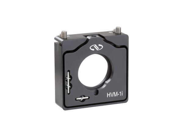 |
| Cause | Mirror mounts in use employed traditional back-mounted actuators | |
| MKS Solution | Changed optical mounts to top adjust industrial mounts | |
| Results | • More efficient use of space inside cytometer • Long-term stability |
|
Example Solution: Low Wavefront Distortion Mounts |
||
|---|---|---|
| Challenge | Not all lasers were focusing to the same point (focal shift issues), leading to sub-optimal SNR | 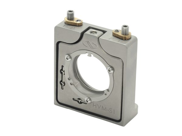 |
| Cause | Too much pressure on beam-combining optics when tightening set screws of mounts ➔ wavefront distortion | |
| MKS Solution | Changed optical mounts to low wavefront distortion mounts | |
| Results | Reduced focal shift ➔ More accurate focusing ➔ Improved signal-to-noise ratio | |
Example Solution: Stainless Steel Mirror Mounts |
||
|---|---|---|
| Challenge | Needed mounts with low thermal drift for long-term stability | 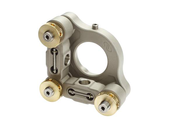 |
| Cause | [new product design] | |
| MKS Solution | Stainless steel mounts with lockable hex-adjustment screws | |
| Results | Long-term stability as a result of • Low coefficient of thermal expansion • Adjustments locked into position |
|
Example Solution: Fluorescence Optical Filters |
||
|---|---|---|
| Challenge | Additional optics added to an existing system could affect other channels | 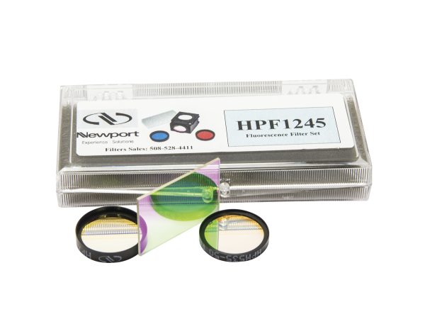 |
| Cause | New laser line added to instrument to allow for use with a larger range of dyes | |
| MKS Solution | A matched set of custom-sized high transmission, high OD optical filters with steep transitions | |
| Results | • High signal-to-noise ratio for new laser line, without affecting other channels • Existing hardware could be used to test the new filters |
|
Example Solution: Aspheric Condenser Lens |
||
|---|---|---|
| Challenge | Too large of a footprint of the instrument | 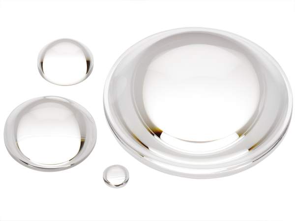 |
| Cause | Too long of an optical path caused by too many lenses used to focus light onto cells | |
| MKS Solution | Replaced multiple spherical lenses with a single aspheric lens with antireflection coating | |
| Results | • Reduced footprint (reduced optical path) • Higher transmission (AR coating & fewer lenses) ➔ Improved signal-to-noise ratio |
|
Example Solution: Motorized Mirror Mounts |
||
|---|---|---|
| Challenge | Flow control nozzle requirement of <10 µrad pointing accuracy not being met ➔ increased in-person field service | 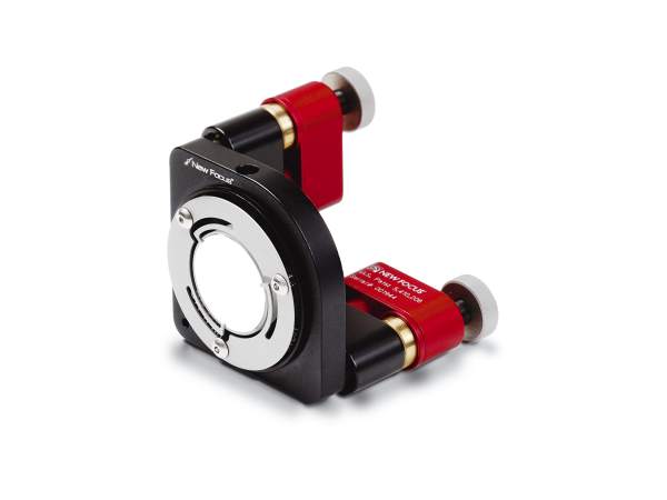 |
| Cause | Not enough holding force keeping flow control nozzle in place during shipment | |
| MKS Solution | Designed a mirror mount with motorized Picomotor™ piezo actuators to hold the flow control nozzle | |
| Results | • Pointing accuracy <1 µrad • Increased holding force ➔ reduced shipment issues ➔ fewer service calls |
|
Example Solution: Motorized Positioners |
||
|---|---|---|
| Challenge | Internal beam routing was experiencing beam drifts ➔ increased in-person field service to realign beam routing | 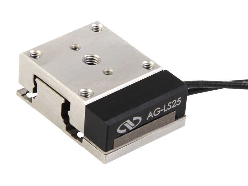 |
| Cause | Challenging environment led to temperature fluctuations | |
| MKS Solution | Motorized, compact linear positioners to realign beam routing optics | |
| Results | Technicians could realign beam routing through their PC ➔ fewer service calls | |
Example Solution: Complete Components Provider |
||
|---|---|---|
| Challenge | Manufacture a designed system | 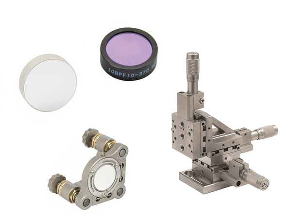 |
| Cause | Not the expertise of the designer | |
| MKS Solution | Provided mirror mounts, mirrors, optical filters and manual positioners | |
| Results | Flow cytometer operating to requirements | |
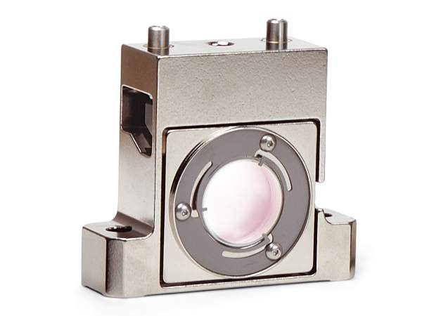
Example Solution: Stable Mounts and Positioners |
||
|---|---|---|
| Challenge | Needed stable alignment in a space-contrained area | 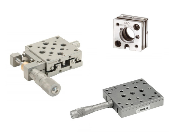 |
| Cause | [new product design] | |
| MKS Solution | Stainless steel flexure mounts and stainless steel manual positioners | |
| Results | Long-term stability within allowable space | |
MKS Products for Flow Cytometry
The table below summarizes typical requirements for flow cytometry systems. Contact us to discuss specific needs of the system in your application.
| Entry Level | Standard Commercially Available | State-of-the-Art | |
|---|---|---|---|
| # of Light Sources | 1 | 1 to 5 | 1 to 16 |
| # of Emission Wavelengths | 1 | 1 to 5 | 4 to 16 |
| # of Components | 5 to 20 | 5 to 100 | 10 to 250 |
| Alignment Accuracy | Microns | Nanometers | Nanometers |
| Bandpass Filters | Not always needed | Required | Critical, with steep transitions |
| Low Wavefront Distortion Mounts | Not as important | Required | Critical |
Check out MKS recommended products for flow cytometry below and select products that best fit your system.
Opto-Mechanics
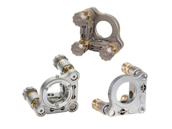
- Suprema® Stainless Steel Mirror Mounts: the industry's best thermal performance for long-term stability.
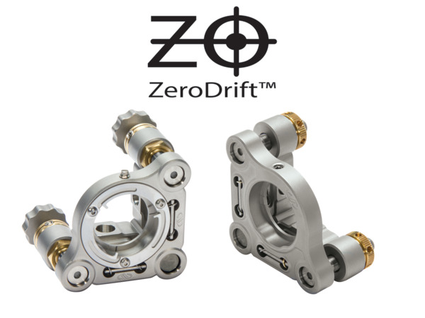
- Suprema® ZeroDrift™ Mirror Mounts: 85% improved optical pointing stability through thermal drift compensation.
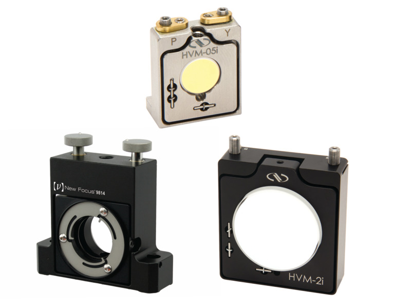
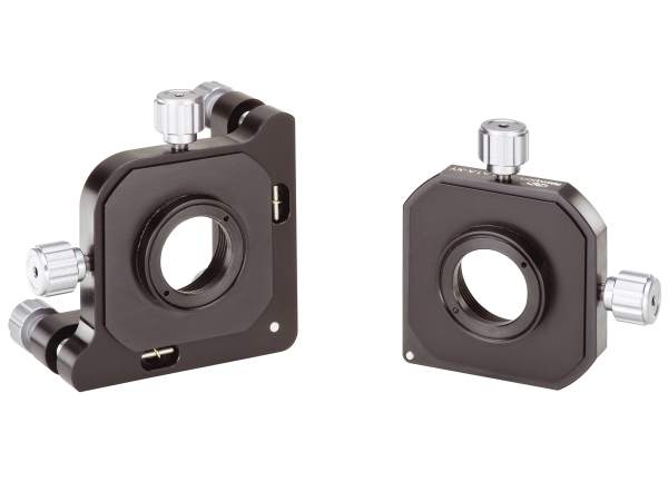
- HVM Top-Adjust Industrial Mirror Mounts: for use in compact spaces so your hands do not have to cross the beam path for adjustment.
- Performa-i Mirror Mounts: economic, industrial mirror mounts optimized for OEM applications.
 Suprema |
 Suprema ZeroDrift |
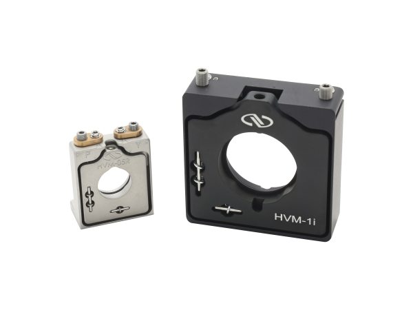 HVM Top-Adjust |
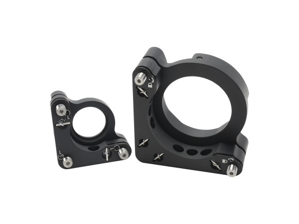 Performa-i |
|
|---|---|---|---|---|
| Optic Diameters | 0.5, 1 and 2 in. | 0.5 and 1 in. | 0.5, 1 and 2 in. | 0.5, 1 and 2 in. |
| Resolution | 50, 100, 127 and 254 TPI | 100 TPI | 80 and 100 TPI | 80 and 100 TPI |
| Angular Range | ±4° to ±7° | ±4° | ±2.5°, ±3° and ±3.5° | ±3° and ±4° |
| Material | Stainless Steel | Stainless Steel | Stainless Steel Anodized Aluminum |
Anodized Aluminum |
| Drive Types | Knob Hex Key |
Knob Hex Key |
Hex Key | Hex Key |
| Lockable Versions | Yes | Yes | Yes | Yes |
| Low Wavefront Distortion Versions | Yes | Yes | Yes | No |
| Other Features | Clear-Edge Version Front- and Rear-Loading Versions Right- and Left-Handed Configurations |
Thermal drift compensation Front- and Rear-Loading Versions |
Slim Profile Alignment Pin Holes Front- and Rear-Loading Versions |
Slim Profile Threaded Aperture Version for Thin Optic Right- and Left-Handed Versions |
- Picomotor™ Piezo Mirror Mounts: automated, ultra-fine resolution adjustments.
| Picomotor™ Piezo | ||
|---|---|---|
| Optic Diameters | 1, 2, 3 and 4 in. | 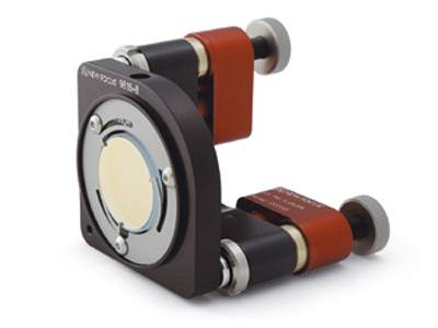 |
| Angular Range | ±3°, ±3.5°, ±4° and ±5° | |
| Resolution | 0.7 µrad angular | |
| Material | Anodized Aluminum | |
| Drive Types | Picomotor Actuator | |
| Lockable | No, but no movement when no power is applied | |
| Low Wavefront Distortion Versions | Yes (Stability™ series) | |
| Other Features | Clear-Edge Version Right- and Left-Handed Configurations |
- LP Precision Multi-Axis Lens Positioners: highest performing lens positioners.
- Compact Lens Positioners: ideal solution for applications with limited space.
- LT Lens Tubes: combine several optical components into stable, rigid assemblies.
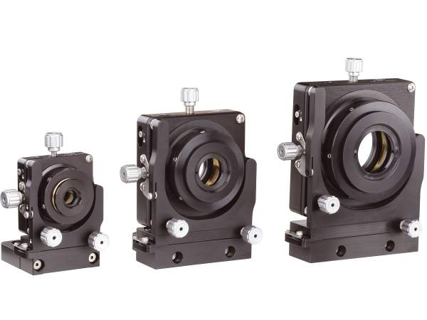 Precision LP |
 Compact LP |
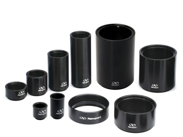 Lens Tube |
|
|---|---|---|---|
| Optic Diameters | 0.5, 1 and 2 in. | 1 in. | 0.5, 1 and 2 in. |
| Resolution | 100 TPI (Z-axis: 80 TPI) | 100 TPI (Z-axis of 9841: 80 TPI) | |
| Adjustments | XY XYZ XYZ θxθy |
XY XYZ XYZ θxθy |
|
| Material | Aluminum | Aluminum | Aluminum |
| Drive Types | Knob w/ Hex Hole & Knurled Ring | Knob w/ Hex Hole (9841: Knob Only & Knurled Ring) |
|
| Lockable Versions | Yes | Yes | |
| Other Features | Zero-free play XY mechanism Adapters for other optics |
Adapters for other optics Optional lock nuts |
Many accessories and adapters |
Custom Component and OEM Design
If our standard products satisfy most of your requirements but maybe not all of them, we have the ability to customize them for your needs. MKS has designed thousands of opto-mechanical and positioning products for many decades, so we have the expertise to provide the optimal solution for your application.
One type of customization we’ve done over and over is modifying one of our standard products so that it can exactly meet your needs. We also call this a “same-as-except” type of component. Some examples include:
- Adding mechanical characteristics to meet space constraints or mounting requirements of your system, such as adding alignment pinholes
- Modifying mounts to hold non-standard sized optics or non-optical components such as flow cells, sensors, or laser diode modules
- Inserting higher or lower tensions springs
- Increasing the travel range of a positioner
Another modification we can make to our components is to use materials, lubricants, adhesives and other design features and manufacturing processes so that they can meet challenging and extreme environments, such as vacuum and cleanroom.
We can build-to-print from your own design or help you build entirely new products, whichever is the preferred method of a partnership that you choose. In addition to our design expertise, we have extensive testing capabilities to make sure the products will perform, and we have full ISO certification for our world-class operations.
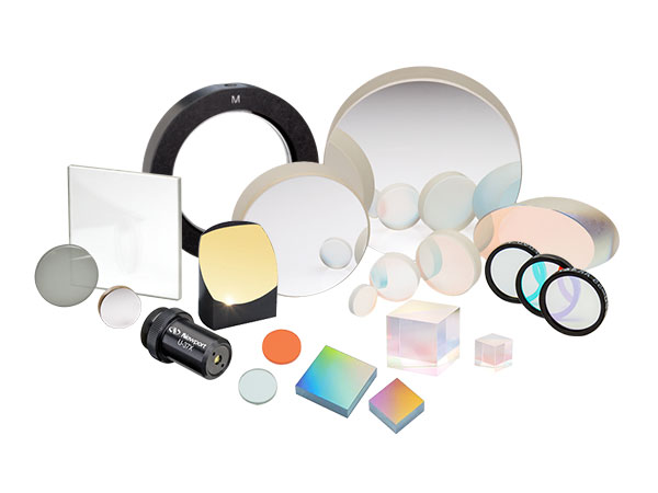
Optics
- HPF Filter Sets for Fluorescence Microscopy: maximum imaging performance for fluorescence detection of the most popular and promising fluorophores.
| Filter Type | Excitation | Dichroic | Emission | |
|---|---|---|---|---|
| Passband Transmittance | ≥90% | ≥90% | ≥90% | 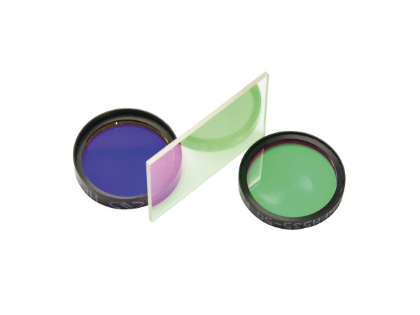 |
| Dichroic Reflectance | N/A | ≥90% | N/A | |
| Spectral Blocking | ≥OD6 | N/A | ≥OD6 | |
| Size | Ø25 mm | 25.5 x 36 mm | Ø25 mm | |
| Spectral Response | Stable performance @ 0% to 100% RH | |||
| Coating Operating Temperature | -100° C to 300° C | |||
| Other Features | Coating hardness, abrasion resistance, adhesion, and humidity to MIL standards | |||
Custom Fluorescence Filter
MKS has been manufacturing optical filters for over 50 years. This includes providing unsurpassed fluorescence filter solutions for applications such as flow cytometry, DNA sequencing, in-vivo imaging, and other fluorescence-based instrumentation.
Our filters are manufactured with our ODiate™ or Stabilife coating coating technologies to cover all performance ranges. We use proprietary processes for the deposition of thin film coatings—up to hundreds of layers with ODiate—which produce highly dense thin film coatings with extraordinary hardness, abrasion resistance and adhesion to the substrate. As a result of our manufacturing processes and experience, we are able to deliver filters with extremely high transmission, steep transitions from transmission to rejection, and superior image quality. Additionally, our filters provide very high spectral stability over temperature and humidity changes.
| ODiate | Stabilife | |
| Wavelength Range | 340-1800 nm | 250-2100 nm |
| Edge Transition | 0.5% | 2% |
| Peak Transmission | 99% | 93% |
| Out of Band Blocking | OD8 | OD6 |
| Wavelength Accuracy | ±0.25% | ±3% |
| Losses Due to Scatter & Absorption | < 1% | 3% |
| Transmitted Wavefront Error | 0.01λ RMS | 0.1λ RMS |
We can custom design and manufacture filters that meet your application's requirements. We'll work with you to understand the kind of performance specs, size and shape you need, whether it's for emission bandpass, excitation bandpass or dichroic filters. And the quantities we can provide are scalable as your needs grow.
- Aspheric Condenser Lenses: combine the performance of multiple spherical lenses to reduce the optical path length and number of components.
| Aspheric Condenser Lenses | ||
|---|---|---|
| Wavelengths | MgF2 coated: 400-700 nm Uncoated: Visible to NIR |
|
| Avg. Reflectivity per Surface | <1.5% MgF2 coated 4% uncoated |
|
| Diameters | 6.8 to 75 mm | |
| Effective Focal Lengths | 5.87 to 49.24 mm | |
| Shapes | Plano-Convex Bi-Convex |
|
| Substrate Materials | Schott B 270® Ultra-White Glass | |
| Other Features | Reduced Spherical Aberration Molded Fabrication |
- Broadband Metallic Mirrors: good performance and value over very broad spectral ranges.
| Wavelengths | 250-600 nm | 450-700 nm | 480-20000 nm | 650-20000 nm | |
|---|---|---|---|---|---|
| Coatings | UV Aluminum | Aluminum | Silver | Gold | 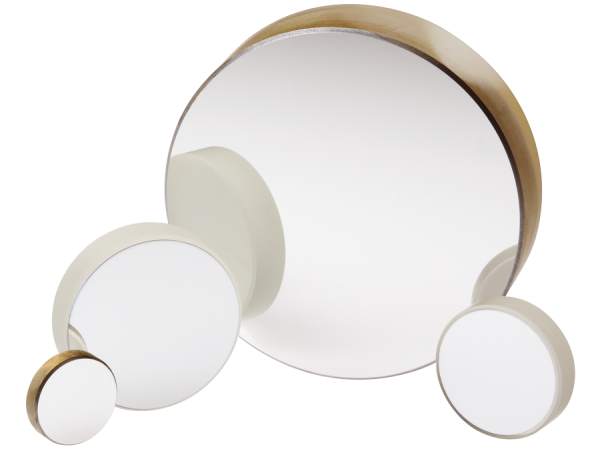 |
| CW Damage Threshold | 100 W/cm2 | 100 W/cm2 | 1000 W/cm2 | 200 W/cm2 | |
| Reflectivity | >90% | >93% | >96% | >96% | |
| Diameters | 0.5 to 8 in. | ||||
| Other Shapes | Square, Elliptical, D-shaped, Concave | ||||
| Substrate Materials | Borofloat 33, Zerodur | ||||
| Other Features | Insensitive to polarization and AOI | ||||
Positioners
- Gothic Arch Ball Bearing Linear Stages: automated, nanometer-scale movement and least susceptible to shock.
- Agilis™ Piezo Motor Linear Stages: automated, fast nanometer-scale movement in a compact package.
- Super Agilis™ High Speed Piezo Motor Linear Stages: automated, super fast nanometer-scale movement in a compact package.
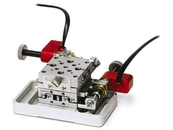 906x Series |
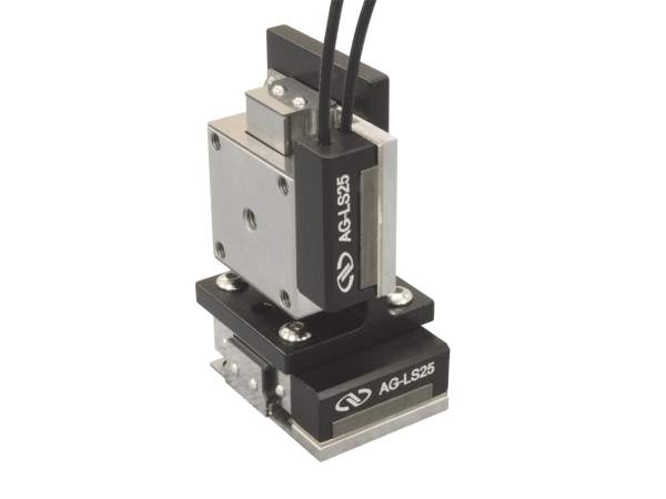 Agilis™ |
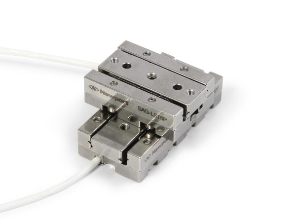 Super Agilis™ |
|
|---|---|---|---|
| Drive Type | Picomotor™ | Piezo Motor | Piezo Motor |
| Travel Range | 5, 12.7 and 25.4 mm | 12 and 27 mm | 16, 32 and 48 mm |
| Minimum Step Size | <30 nm | 50 and 100 nm | 25 nm (closed-loop) 100 nm (open-loop) |
| Angular Deviation | <100 µrad | <200 µrad | <150 µrad |
| Speed | 0.02 mm/s | 0.5 mm/s | 10 mm/s |
| Bearings | Ball | Ball | Crossed-Roller |
| Material | Stainless Steel | Stainless Steel | Stainless Steel |
| Other Features | Pre-assembled XY and XYZ configurations Picomotor and Micrometer combined driven versions |
Holding force locks position when idle Closed-loop controller version |
Holding force locks position when idle Includes controller |
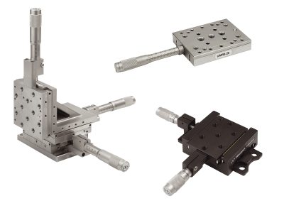
- ULTRAlign™ Crossed-Roller Bearing Steel Linear Stages: highest smoothness, precision and stability.
- Industrial Dovetail Aluminum Linear Stages: very high stability in a compact, economic package.
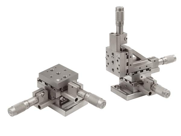 Ultralign |
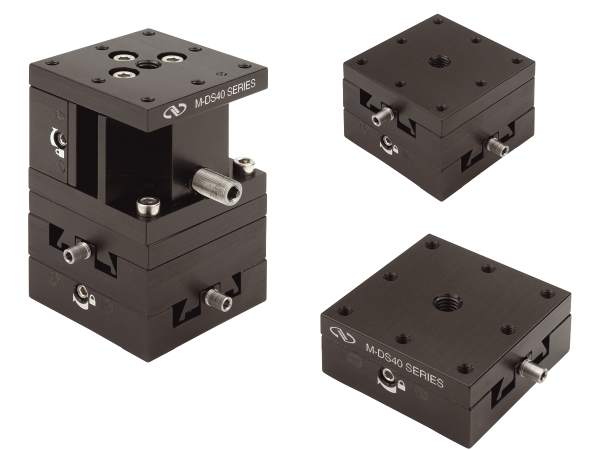 Industrial DS |
|
|---|---|---|
| Travel Range | 13 and 25 mm | 6.35, 14 and 25.4 mm |
| Axes of Travel | X, Z, XY, XZ and XYZ | X, Z, XY and XYZ |
| Angular Deviation | <100 µrad | |
| Bearings | Crossed-Roller | Dovetail |
| Material | Stainless Steel | Aluminum |
| Drive Type | Adjustment Screw Micrometer Motorized Actuator |
Hex Key |
| Lockable | Yes | Yes |
| Other Features | Extra thick plates for more stability Low profile Right- and left-handed configurations |
LaserClean™ Version Right- and left-handed configurations |
Lasers
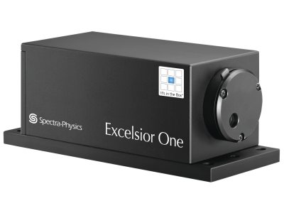
- Excelsior® One™ CW Lasers: largest portfolio of up to 12 different wavelength options with laser head and controller in a single, compact package.
- Vanguard™ One™ Quasi-CW UV Lasers: Compact UV laser for flow cytometry and bio-instrumentation applications requiring higher power.
| Excelsior® One™ CW Laser | ||
|---|---|---|
| Output Power | 10 mW to 500 mW (adjustable) | 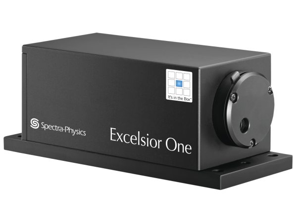 |
| Wavelengths | 375 to 1064 nm (free space) | |
| Linewidth | <0.01 pm to <1.5 nm | |
| Beam Pointing Stability | <6 µrad/°C | |
| Power Stability | <±2% over 8 hours | |
| Dimensions | 100 x 40 x 40 mm (3.94 x 1.57 x 1.57 in.) |
|
| Other Features | Fiber-coupled option Multi-mode and single freq options RS-232 software interface |
| Vanguard™ One™ Quasi-CW UV Lasers | ||
|---|---|---|
| Output Power | 125 mW | 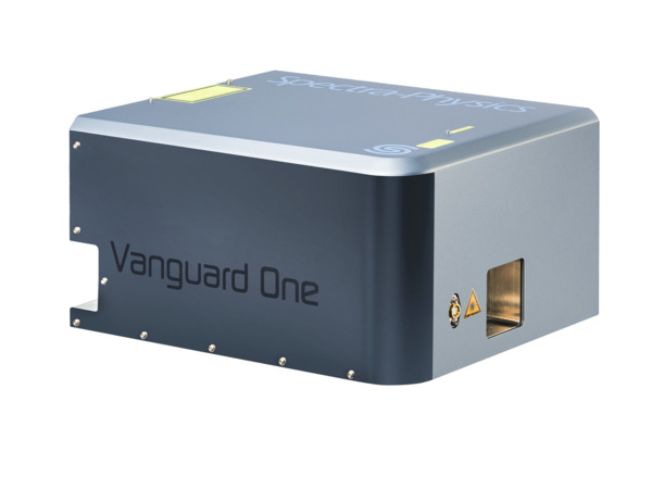 |
| Wavelengths | 355 +/-1 nm (free space) | |
| Pulse Energy Noise | <1% rms | |
| Beam Pointing Stability | <25 µrad/°C | |
| Average Power Stability | <2% | |
| Dimensions | 313 x 259 x 169 mm (12.3 x 10.2 x 6.65 in.) |
|
| Other Features | Air cooled, heat dissipation (100W typical) M2 = 1.2 TEM00 |
Detectors and Power Meters
- 918D-ST Series Detectors: advanced photodiode detector with lowest uncertainty available.
| Spectral Range | 400-1100 nm | 200-1100 nm | |
|---|---|---|---|
| Detector Material | Si | UV Enhanced Si | 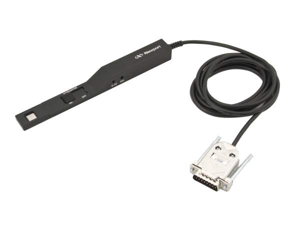 |
| Sensor Size | 10 x 10 mm | ||
| Max Measurable Power (w/ OD3 attenuator) |
2 W | 200 mW | |
| Min Measurable Power (w/o attenuator) |
20 pW | ||
| Calibration Uncertainty (w/o attenuator) |
±1% to ±4% | ||
| Rise Time | ≤3 µs | ||
| Other Features | Switchable OD3 attenuator DB15 connector |
||
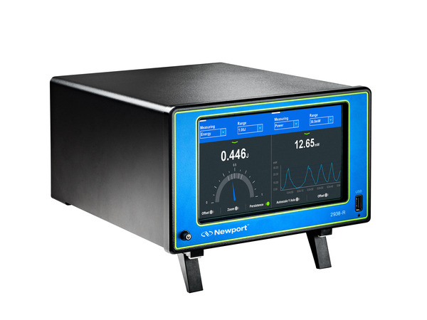 1938-R Touchscreen Power Meter |
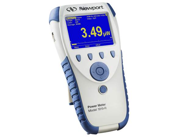 1919-R Handheld Power Meter |
|---|---|
|
|
Resources
Flow Cytometry Brochure(7.1 MB, PDF)

For additional insights into photonics topics like this, download our free MKS Instruments Handbook: Principles & Applications in Photonics Technologies
Request a Handbook