Approximating Real-World Beam Deflection

Newport’s Maximum Relative Motion formula provides an excellent approximation of maximum (worst-case) table top deflection. This technical note explains and quantifies the relationship between Maximum Relative Motion and actual beam deflection in real-world applications.

A simple setup that illustrates beam deflection
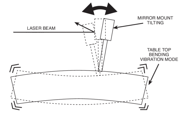
Figure 1. A simple setup that illustrates beam deflection.

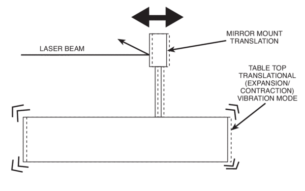
A simple setup illustrates the examples that follow: a mirror mount attached to a table top. A laser beam reflected in the mirror will be affected by two types of table top vibrational modes: axial deflection from translational (expanding/contracting) table top motion and angular deflection caused by table top bending motion. The relative contributions of each mode are generalized under two principles, and a quick method for estimating beam deflection directly is included.

Principle 1: Table top deflection is not a problem, as long as the displacement is in translation

Translational motion of the table top does not affect even sensitive systems
Figure 2. Translational motion of the table top does not affect even sensitive systems.

The maximum deflection of the table top surface is calculated with the Maximum Relative Motion formula:

Translational motion of the table top does not affect even sensitive systems

This formula yields the worst-case deflection for the table top or breadboard where:

δ = worst-case (maximum) deflection of the table top

g = acceleration due to the Earth’s gravity (386 in./sec2)

Q/fn3 = the Dynamic Deflection Coefficient of the table (specified for all Newport tables and breadboards, but can also be derived from any compliance curve)

PSD = power spectral density at fn

Using this formula, we can see how the table deflection affects a mirror mounted to a table top.

Example:

Consider again the vibrational response of a 4 ft. x 8 ft x 12 in. (1200 x 2400 x 305 mm) Newport RS 2000™ table. Using a realistic PSD of 1 x 10⁻⁹g2/Hz, the maximum table deflection is:

Translational motion of the table top does not affect even sensitive systems

This calculated translational displacement is about one-third of a millionth of an inch, or about 0.013 waves of HeNe laser light. This deflection would not normally be a concern in most experiments or applications.

Principle 2: Table top angular deflection is a far more significant contributor to beam deflection

Table top bending is the most significant cause of beam deflection
Figure 3. Table top bending is the most significant cause of beam deflection.

A more serious situation arises when the slope of the table top is considered in the calculation. When a table top or breadboard is affected by vibration, it not only exhibits translational modes, it also has bending modes. Table top bending can have serious consequences for optical performance for two reasons:

  • When a mirror is rotated, the angle of the reflected beam is twice the tilt angle.
  • The “doubled” error also increases linearly with reflected spot distance from the mirror, or:

δtilt = θmirror x ×

Where:

δtilt = spot displacement

θmirror = mirror tilt angle

× = distance from the mirror to spot

For example, a tilt of only one milliradian (1 x 10⁻³ radian) of a flat mirror at a distance of one meter produces a shift in the reflected beam of 2 mm!

Note: We greatly appreciate the participation of Dr. Daniel Vukobratovich of the Optical Sciences Center at the University of Arizona who supplied this mathematical treatment.

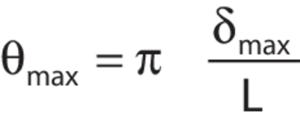
The maximum slope of the table is also quite easy to determine. As an example, consider a 4 ft x 8 ft x 12&in. (1200 x 2400 x 305 mm) Newport RS 2000™ table. The table is supported at each corner and is excited by a PSD of 10-9g2/Hz. In this idealized case the table acts like a simply supported, uniformly loaded beam, and maximum surface slope is related to maximum table deflection by:

Translational motion of the table top does not affect even sensitive systems

Where:

θmax = maximum surface slope

δmax = maximum surface deflection

L = table length

From the previous example, the maximum table deflection was 331 x 10-9 in. So the maximum table slope is:

Translational motion of the table top does not affect even sensitive systems

To determine the effect this will have, consider a flat mirror reflecting a beam over 40 in. (~1 m). The shift in spot location is then:

δ = 2 x (10.8 x 10-9) x 40 = 867 x 10-9 in.

The beam deflection is slightly less than one millionth of an inch. This effect, multiplied by the number of mirrors in the system and the total path length, can have a significant effect on experimental results if the table does not provide an adequate level of vibration-control performance. For example, a total relative movement of five millionths of an inch can seriously degrade the image quality of a diffraction-limited optical system with a numerical aperture of 0.25. This level of deflection can also completely ruin the exposure of a hologram.

Calculating Spot Deflection for any Table Top or Breadboard

Combining the equations for reflected spot deflection and table deflection yields an excellent approximation for the displacement of a spot reflected in a mirror for any table top or optical breadboard:

Translational motion of the table top does not affect even sensitive systems

Where:

δ = motion of the reflected spot in inches

x = distance of the reflected spot from the mirror, in inches

L = table length, in inches

Q/fn3 = dynamic deflection coefficient of table top or breadboard

PSD = power spectral density at table top’s natural frequency

Example:

As a check, this equation will be used to calculate spot motion in the last example. The parameters are then:

x = 40 in.

L = 96 in.

Q = 5

fn = 190 Hz

PSD = 1 x 10⁻⁹g2/Hz

Then the deflected spot displacement is:

Translational motion of the table top does not affect even sensitive systems

This is essentially the same result that was obtained before.