Tunable Light Sources: A Popular Choice for Measurement Applications
Common goals of spectroscopy applications such as studying the chemical or biological properties of a material often dictate the requirements of the measurement system’s lamp, power supply, and monochromator.
Many common spectroscopic measurements require the coordinated operation of a detection instrument and light source, as well as data acquisition and processing. Integration of individual components can be challenging and various applications may have different requirements. Conventional lamp- based tunable light sources are a popular choice for applications requiring a measurement system with this degree of capability.
Many types of tunable light sources are available, with differences in individual component performance translating to the performance of the system as a whole. Tunable light sources are finding themselves to be an especially ideal system for one ap- plication in particular: quantum efficiency and spectral responsivity characterization of photonic sensors, such as solar cells.
The tunable light source’s (TLS) versatility as both a broadband and high resolution monochromatic light source makes the unit suitable for a variety of applications, such as the study of wavelength-de- pendent chemical or biological properties or wavelength-induced physical changes of materials. These light sources can also be used in color analysis and reflectivity measurements of materials for quality purposes.
Among their unique attributes, the TLS can produce monochromatic light from the UV to NIR. Lamp-based TLSs feature two major components: a light source and a monochromator. Common lamps used in TLSs are the DC arc lamp and quartz tungsten halogen (QTH) lamp. While both of these lamps have a broad emission spectrum, arc and QTH lamps differ in the characteristic wavelength emissions or relatively smooth shape of their spectral output curves, respectively. A stable power supply for the lamp is a critical component since most applications require high light output power stability
Smooth Spectral Output vs. Monochromator Throughput
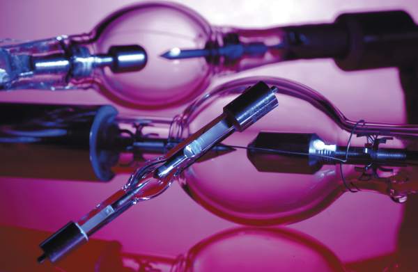
DC arc lamps are excellent sources of continuous wave, broadband light. They consist of two electrodes (an anode and a cathode) separated by a gas such as neon, argon, mercury, or xenon. Light is generated by ionizing the gas between the electrodes. The bright broadband emission from this short arc between the anode and cathode makes these lamps high-intensity point sources, capable of being collimated with the proper lens configuration.
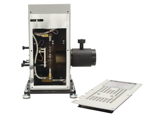
DC arc lamps also offer the advantages of long lifetime, superior monochromator throughput (particularly in the UV range) and a smaller divergence angle. They are particularly well-suited for fiber coupling applications2 (Figure 2).
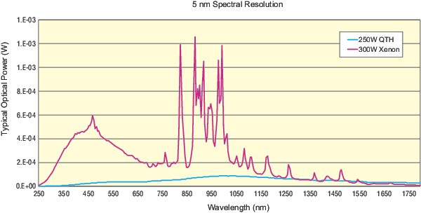
Xenon (Xe) arc lamps, in particular, have a relatively smooth emission curve in the UV to visible spectrums, with charac- teristic wavelengths emitted from 380 to 750 nm. However, strong xenon peaks are emitted between 750 to 1000 nm. Their sunlike emission spectrum and about 5800 K color temperature make them a popular choice for solar simulation applications (Figure 3).
Arc lamps can have the following specialty characteristics:
- Ozone-free: Wavelength emissions below about 260 nm create toxic ozone. Ideally, an arc lamp is operated outdoors or in a room with adequate ventilation to protect the user from the ozone created.
- UV-enhanced: For applications re- quiring additional UV light intensity, UV- enhanced lamps should be used. These lamps provide the same visible to NIR performance of an arc lamp while providing high-intensity UV output due to changes in the material of the lamp’s glass envelope.
- High-stability: High-stability arc lamps are made of a higher quality cathode than that typically used for arc lamp construction. As a result, no arc wander occurs, allowing the lamp to maintain consistent output intensity throughout its lifetime.
QTH lamps produce light by heating a filament wire with an electric current. The hot filament wire is surrounded by a vacuum or inert gas to prevent oxidation. QTH lamps are not very efficient at con- verting electricity to light, but they offer very accurate color reproduction due to their continuous blackbody spectrum. These lamps are a popular alternative to arc lamps due to their higher output intensity stability and lack of intense UV light emission, spectral emission lines in their output curve, and toxic ozone production. These features make QTH lamps ideal for radiometric and photometric applications as well as excitation sources of visible to NIR light. QTH lamps are also easier to handle and install, and produce a smooth output spectrum. Selecting the most ap- propriate lamp type is a matter of deciding which performance criteria are most important.
Constant Current vs. Constant Power
The power supply is a vital component for operating a DC arc or QTH lamp with minimum light ripple. The lamps are operated in either constant current or constant power mode and are used in applications such as radiometric measurements, where a stable light output is required for accurate measurement. Providing stable electrical power to the lamp is important since fluctuations in the wavelength and output intensity of the light source impact the ac- curacy of measurement.
There is very little difference in the short-term output stability when operating an arc lamp or QTH lamp in constant current or constant power mode. However, the differences appear as the lamp ages. For arc lamps, even with a stable power supply, deposits on the inside of the lamp envelope are visible as the electrodes de- grade, which causes an unstable arc position, changing the electrical characteristics of the arc lamp. The distance between the cathode and anode of the arc lamp increases, raising the lamp’s operating voltage. For QTH lamps, deposits on the inside of the lamp envelope are visible as the lamp filament degrades, changing the electrical and spectral characteristics of the lamp.
Although power supplies are highly regulated, there are factors beyond the control of the power supply that may affect light output. Some of these factors include lamp aging, ambient temperature fluctuations, and filament erosion. For applications in which high-stability light output intensity is especially critical, optical feedback control of power supply is suggested in order to compensate for such factors3 (Figure 4).
Diffraction Gratings Narrow the Wavelength Band
Monochromators use diffraction gratings to spatially isolate and select a narrow band of wavelengths from a wider wave- length emitting light source. They are a valuable piece of equipment because they can be used to create quasi-monochromatic light and also take high-precision spectral measurements. A high-precision stepper motor typically is used to select the desired wavelength and switch between diffraction gratings quickly, without sacrificing instrument performance.
Determining which slit width to use is based on the trade-off between light throughput and the resolution required for measurement. A larger slit width al- lows for more light throughput. However, more light throughput results in poorer resolution. When choosing a slit width at which to operate the monochromator, both the input and output ports must be set to the same slit width (Figure 5).
Focused light enters the monochromator through the entrance slit, and is redirected by the collimating mirror toward the grating The grating directs the light toward the focusing mirror, which then redirects the chosen wavelength toward the exit slit. At the exit slits, quasi-monochromatic light is emitted.
Transmittance Measurement
Transmittance measurements are per- formed to quantify the amount of light that is capable of passing through a sample at various wavelengths. Light from the tunable light source is shone onto a sample, and then through to the optical detector. Transmittance is expressed as a percentage, with 100% indicating that all light passes through the sample and 0% indicating no light passes through. Prior to performing the transmittance scan, a reference scan is performed. In this case, no sample is in the light path to the detector. This is used as a baseline measurement.
It is important to note that the light must reach the detector when the sample is in place. Leaving the detector in the same location as the reference scan assumes the index of refraction equals 1, so that the light is not bent (which would miss the active area of the detector). It should also be noted that with samples that diffuse light, both the reference and sample scans should be performed by collecting the light with an integrating sphere.
Figure 6 shows a transmittance measurement system where the sample diffuses light. The light is captured using an integrating sphere. Note that the illustration does not show the interior baffle arrangement of the integrating sphere. Be- cause the light needs to bounce off at least two surfaces before striking the detector, the baffle must be placed between the light input port and the detector port. Light directly hitting the active area of the detector will result in measurement errors.
Measuring Quantum Efficiencies
Measuring quantum efficiency (QE) over a range of different wavelengths to measure a device’s QE at each photon energy level is an ideal task for a tunable light source. The QE of a photoelectric material for photons with energy below the band gap is zero. The QE value of a light-sensing device such as a solar cell indicates the amount of current that the cell will produce when irradiated by photons of a particular wavelength. The principle of QE measurement is to count the proportion of carriers extracted from the material’s valence band to the number of photons im- pinging on the surface. To do this, it is necessary to shine a calibrated, tunable light on the cell, while simultaneously measuring the output current. The key to accurate measurement of the QE/internal photon to current efficiency is to accurately know how much scanning light is incident on the device under test and how much current is generated. Thus, measurement of light output with a NIST (National Institute of Standards and Technology) traceable calibrated detector is necessary prior to testing since illumination of an absolute optical power is required.
External quantum efficiency (EQE) is the ratio of the number of photons incident on a solar cell to the number of generated charge carriers. Internal quantum efficiency (IQE) also considers the internal efficiency — that is, the losses associated with the photons absorbed by nonactive layers of the cell. By comparison, EQE is much more straightforward to measure, and gives a direct parameter of how much output current will be contributed to the output circuit per incident photon at a given wavelength. IQE is a more in-depth parameter, taking into account the photo- electric efficiency of all composite layers of a material. In an IQE measurement, these losses from nonactive layers of the material are measured in order to calculate a net quantum efficiency — a much truer efficiency measurement.
Understanding the conversion efficiency as a function of the wavelength of light impingent on the cell makes QE measurement critical for materials research and solar cell design. With this data, the solar cell composition and topography can be modified to optimize conversion over the broadest possible range of wavelengths.
As a formula, it is given by IQE = EQE/ (1 − R), where R is the reflectivity, direct and diffuse, of the solar cell. The IQE is an indication of the capacity of the active layers of the solar cell to make good use of the absorbed photons. It is always higher than the EQE, but should never exceed 100%, with the exception of multiple-exciton generation. Figure 7 illustrates how the tunable light source is used to illuminate the solar cell to perform an IQE measurement. The software controls all components of the measurement system, including the monochromator and data acquisition.
To measure quantum efficiency in 10-nm wavelength steps, the slit size of the monochromator is typically hundreds of microns in width. The slit width is reduced approximately half if 5-nm wavelength increments are desired. However, output power of the monochromator is reduced by more than 50% if the slit width is halved. Lowering optical power impacts QE measurement since a solar cell responds to this diminished optical power with low output current. This can result in a poor signal- to-noise ratio, making a QE measurement error more likely. The detection of low current requires very sensitive equipment with the ability to measure current down high-output power and stability, long life- time of the lamp, and broadband spectral emission with high-resolution capability are required for the TLS.
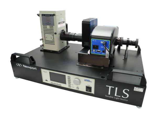
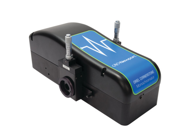
For an optimized solution to these measurement applications, Newport offers the Oriel TLS130B series of tunable light sources as a fully assembled, pre-aligned, and factory-characterized instrument (Figure 8).