Swept-Wavelength Testing

With the recent trend towards higher channel counts in telecommunications systems, the efficiency of wavelength-characterization measurements is becoming a major issue. Although the broadband source and OSA method is fast, it doesn't provide the resolution that is required to characterize complicated devices. Techniques based upon lasers that “step” then measure can provide both the dynamic range and the resolution but are very slow. The swept-wavelength measurement technique, however, is faster than the OSA method and has the resolution of a laser. While this method has applications in the area of final test, it also has significant benefits in the assembly of DWDM components and can provide tremendous cost savings as devices grow in complexity.

To accommodate the high demands of telecommunications networks, the telecommunications community is continually advancing its technology, pushing for narrower channel spacings and/or an expanded wavelength range. Current state-of-the-art, so-called dense-WDM (DWDM) systems are using narrower, 50-GHz (0.4-nm) channel spacings, with companies already discussing even narrower spacing. Moreover, while original WDM systems are limited to the wavelength range from 1530 to 1565 nm, new extended L-band erbium amplifiers allow WDM systems to operate in a window from 1530 to 1615 nm. The result of this increase in the number of WDM channels is a proportional increase in the complexity and duration of time required to fully characterize network components, such as multiplexers and gain-flattening filters, many of which must be characterized not only at the channel of interest, but also over the entire wavelength band. By design, devices in WDM systems have wavelength-dependent optical properties. Therefore many WDM components must be optimized during manufacturing to set their center (or channel) wavelength accurately or to minimize insertion loss across the wavelength range. One example is a multiplexer based on either fiber-Bragg gratings or coated étalon filters. In the fiber-Bragg-grating-based device, applying a small stress to the grating sets the center wavelength. In the device using a coated étalon filter, the center wavelength is adjusted by slightly tilting the optic. Historically, methods such as those using a broadband source and an optical spectrum analyzer (OSA) have been used to monitor component performance during manufacture. Although this method is very fast, the channel spacing and high channel count of DWDM systems is straining the limit of these systems. To achieve higher resolution, a tunable laser and a detector can be used, but stepping the laser across the full range of interest for a multiplexer (MUX) is a lengthy, time-intensive process, limiting this method's use to final device testing only.

In this application note, we will discuss a new method that can significantly decrease the measurement time without sacrificing measurement resolution, delivering the resolution of a laser with the speed of an OSA. In this method the wavelength is swept continuously at a constant rate while the output is recorded, providing a very high-resolution spectral picture—fast enough to observe changes as a component is being adjusted. While this has obvious applications in the final testing and quality control of DWDM components1,2, it also creates a whole new opportunity to improve the manufacture of DWDM components by allowing in-situ testing during the manufacturing process itself. Indeed, the capability of real-time, high-resolution measurements in the assembly environment can significantly improve the production of demultiplexers, multiplexers and other DWDM devices.

The Swept-Wavelength Technique

The swept-wavelength technique has been used in the RF and microwave community for many years. Network analyzers use this combination of a swept source and power meter to characterize insertion loss and return loss in the frequency domain. In the optical regime, a tunable laser continuously sweeps over the wavelength range while the output is recorded. Thus, the main requirement is a tunable mode-hop-free laser that has a very linear and repeatable scan. One laser that satisfies this requirement is the TLB-6600 tunable laser from New Focus™, which was designed specifically for swept-wavelength measurements. It covers both the C- and L-bands and it delivers extremely linear, repeatable mode-hop-free tuning over the entire band and incorporates a patent-pending motor design to ensure highly linear and repeatable scans. It also features an electrical trigger that can trigger detectors when the scan reaches a spectral region of interest, making it easy to monitor wavelength changes of a component in real time and enabling the user to make adjustments with real-time feedback. (This trigger can also be used for displaying the output of the detector on an oscilloscope.) The stability of the wavelength trigger and the repeatability of the scan ensure that motion measured on the oscilloscope is due to the spectral change of the device under test. Finally, the high output power allows the simultaneous measurement of multiple output channels in a device. The other components needed to complete a typical swept-wavelength system includes a high-speed power sensor such as the Model 2103 high-dynamic-range power sensor as the receiver and, for data capture and storage, a data acquisition card such as the National Instruments™ PCI-6110E (5 MS/sec, 4 channels), and a GPIB controller card, such as the National Instruments PCI-GPIB.

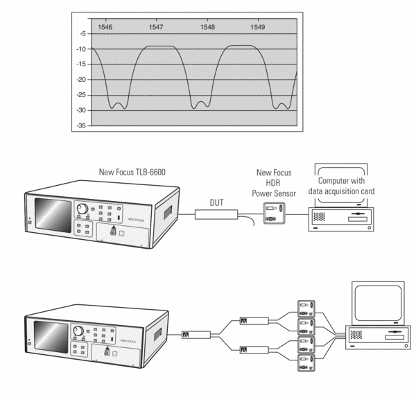
This system, shown in Figure 1, is used to characterize interleavers. Interleavers are used to multiplex or demultiplex DWDM channels. With the swept-wavelength system, measurement of these devices can be performed in just 1 second. The speed and efficiency of this technique therefore enables operators to make adjustments while seeing the results in real time, giving the manufacturer real-time process control. Other examples of how the swept-wavelength technique can be used are addressed in the New Focus Application Notes 8 and 9. Application Note 8, Real-Time Wavelength Trimming of WDM Muxes describes how a Mux using fiber-Bragg gratings might be manufactured by measuring the wavelength shift as a small stress is applied to the fiber. Application Note 9, Measuring Fiber-Bragg-Grating Temperature Drift discusses the measurement of a small temperature drift of a stabilized fiber-Bragg grating.

The wavelength of the laser is swept continuously at a constant rate (up to 2,000 nm/s) while the output is recorded, providing a very high-resolution spectral picture—fast enough to observe changes as a component is being adjusted.

The test system for an interleaver uses a swept-wavelength tunable laser, multiple-channel data acquisition board, and power sensors
Figure 1. The test system for an interleaver uses a swept-wavelength tunable laser, multiple-channel data acquisition board, and power sensors. In Figure 1a, the system is used to test one channel of the device. Figure 1b shows how the test system can be expanded to the desired number of channels by adding more interleavers and more power sensors to the system. For simplicity, the diagram does not show the GPIB connection from the computer to the laser, used to initiate the test, or the trigger connection from the laser to the computer which allows you to record data only for a specified wavelength range.

Comparison to Traditional Wavelength-Characterization Methods

The broadband noise source and OSA technique consists of a broadband source, such as an edge-emitting light-emitting diode (EELED) or the amplified spontaneous emission (ASE) of an erbium fiber amplifier, and an OSA. As stated earlier, this technique is fast (a typical scan can take 1 second) and has a very wide wavelength range (>50 nm). However, its relatively low wavelength resolution (typically 0.1 nm due to limitations of the OSA) makes it unsuited to characterize some critical DWDM components. For example, consider a demultiplexer in a 50-GHz system with 80 channels; with the requirement that the isolation between channels is over 30 dB that is, the device loss at 0.4 nm from line center is at least 30 dB the measurement requires a resolution of 0.01 nm (10 pm). Nonetheless, the OSA method does offer superb dynamic range because the OSA acts as a non-wavelength-selective light source. Thus this method has been used successfully in the subcomponent assembly level where a relative measurement is sufficient. The speed of the instrument allows technicians to optimize the alignment of subcomponents. Despite its limited resolution, this method is acceptable for devices that have little spectral information, such as isolators or taps. Devices that have more intricate wavelength dependencies require more complex methods.

In contrast, the step-and-measure method does provide high resolution by using a tunable optical source, usually an external-cavity diode laser, and a power meter or detector. This method shares the same high-resolution, high-power capability of the swept-wavelength method. However, it is considerably slower because in this case the laser is stepped incrementally over the desired wavelength range and the optical throughput is measured at each step. In this case, the laser stops at each measurement point for a given amount of time. For instance, for a broadband device covering the wavelength range from 1520-1570 nm with 1-nm resolution, you'll need about 50 measurements. Taking 400 ms as the average step time, this type of scan will take 20 seconds. A narrowband device like a drop filter will require a 10-pm resolution over 3 nm for 300 measurement points and a few-minute measurement. Finally, an 80-channel demultiplexer for a 50-GHz system must look at the actual shape as well as the isolation over neighboring channels. Covering the 35-nm wavelength span with 0.01-nm resolution means the measurement must cover 3500 points, which will take about 20 minutes and this is just for a single output channel of the device at a single polarization. For polarization-dependent effects, the four Stokes parameters must be measured, taking at a minimum four times longer to measure.

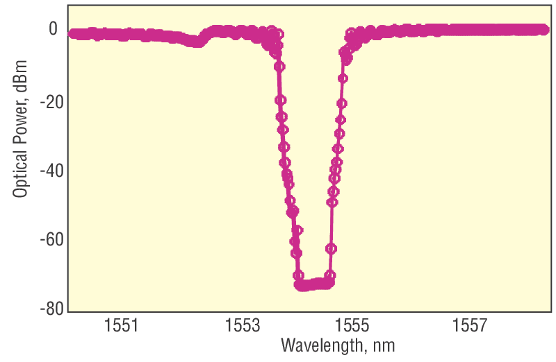
In comparison, the swept-wavelength technique with a New Focus™ TLB-6600 laser scanning at 2,000 nm/s takes less than 0.1 seconds to cover the 35-nm wavelength range. Low-noise swept-wavelength lasers are now available with wavelength integrated dynamic ranges of >60 dB providing low-noise measurement capability. Understanding the noise spectrum of a laser is important since its noise characteristics will limit the dynamic range of your measurements. Yet each laser specifies the noise differently. That's why at New Focus we specify our lasers in a few different ways so that you can make accurate comparisons. First we specify the amplified spontaneous emission (ASE) at two distances away from the carrier by using an OSA at resolution bandwidths (RBWs) of 0.1 nm and 0.2 nm. In addition, we specify the signal-to-ASE ratio, integrated over all wavelengths. This is especially important because receivers are insensitive to wavelength and so integrate all the incident power regardless of wavelength. We measure this integrated dynamic range by observing the spectrum of two cascaded fiber-Bragg gratings with a total rejection ratio of >100 dB and a 0.8-nm window. See Figure 2. The fiber-Bragg gratings reject the laser-carrier wavelength while transmitting most of the ASE. The power meter used to measure the ASE has a >90-dB dynamic range. As the laser wavelength is scanned across the fiber-Bragg gratings, the measured rejection ratio is limited only by the noise spectrum of the laser and is a measurement of the ratio of the signal to the total integrated source emission outside the 0.8-nm bandwidth of the filter.

This is the achievable wavelength-integrated dynamic range and is a realistic expectation of what you'll see in your lab. So when you're comparing ASE or dynamic range specifications, remember to ask:

  1. Was the measurement taken with an OSA? If so, what was the resolution bandwidth?
  2. How far away from the carrier?
  3. Over what wavelength range?
  4. What is the integrated signal-to-noise ratio?
  5. How far away was this measurement from the carrier? Over what wavelength range? What method was used?
Optical power transmission through two matched narrow-notch-filter fiber-Bragg-grating reflectors measured with the our swept-wavelength laser
Figure 2. Optical power transmission through two matched narrow-notch-filter fiber-Bragg-grating reflectors measured with the our swept-wavelength laser. The ratio of the signal power to the total integrated ASE-background power outside the 0.8-nm filter width is >70 dB. NOTE: An OSA will slow down your measurement and is not ideal for swept-wavelength measurements. Detection systems should have bandwidths of a few 100 kHz.

References

  1. Nyman, Bruce, DWDM Component Characterization, NIST Symposium on Optical Fiber Measurements, (Sept. 1998), p. 1.
  2. Nyman, Bruce, Four measurement methods characterize WDM components, OptoElectronics World, (Sept. 1998), p. S2.
  3. Application Note 10: Swept-Wavelength Testing: Saving Time and Bringing Real-Time Process Control to the Manufacturing Environment
  4. Swept-Wavelength Tunable Lasers - TLB-6600 Venturi™ Swept-Wavelength Tunable Lasers