Stage Components Considerations
Choosing the right positioning technology for an application is a complex task. There are numerous choices of linear stages, rotation stages and actuators and each product has its own advantages and disadvantages. The specifications of a stage are certainly important selection criteria. However, the specifications might neither be exhaustive enough nor directly applicable for each application. For this reason, it is important to have sufficient understanding of the inherent abilities of the components that make up a stage. Newport provides detailed descriptions for all stages to help make the right choices. The purpose of this section is to provide a brief discussion of the most common components used in high precision positioning equipment with their pros and cons.
Bearings provide smooth low-friction rotary or linear movement between two surfaces. They are the primary elements that determine the run-out errors of a stage, namely Straightness, Flatness, Pitch, Roll and Yaw for linear stages or eccentricity and wobble for rotation stages. The bearings define also the stiffness of the stage, but not in the direction of travel, and the static load capacity of a stage. The dynamic load capacity, however, is primarily limited by the rigidity of the drive train and the power of the motor, and not by the bearings.
Also, in order to get optimum performance, the surface of the carriage and the body to which the bearings are attached needs to match the same quality as the bearings.
Dovetail Slides
Dovetail slides are the simplest type of linear stages and are primarily used for manual positioning. They consist of two flat surfaces sliding against each other with the geometry shown in Figure 1. Dovetail slides can provide long travel, and have relatively high stiffness and load capacity. They are more resistant to shock than other types of bearings and are fairly immune to contamination. However, they do have relatively high stiction, and the friction varies with translation speed, which makes precise control difficult and limits sensitivity.
Ball Bearings
Ball bearing slides reduce friction by replacing sliding motion with rolling motion. Balls are constrained by vee-ways or hardened steel rods, as shown in Figure 2. The bearing ways are preloaded against the balls to eliminate unwanted runout in the bearings. Even with this preload, the friction is very low resulting in extremely smooth travel. Ball bearing slides are relatively insensitive to contamination because each ball contacts the guide ways at only a single point, allowing debris to be pushed out of the way.
Since the contact area available to transmit loads is smaller in vee-grooved bearing ways, ball bearings have a lower load capacity than crossed-roller or other bearings. In order to carry the same sized load, the balls would need to be larger in diameter or be greater in quantity. If the bearing ways are ground with an arch or circular groove (see Figure 3), the closer the conformity to the balls' radii increases the contact area. This allows the use of smaller balls than with flat ways.
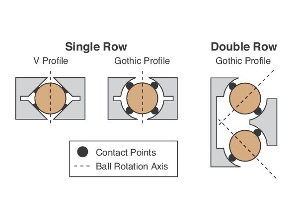
Most ball bearing slides make 4 contact points with the bearing ways with a 45° angle to the axis of the ball rotation. Although this provides an equal load ratio, it also introduces some differential slip as those contact points of the bearings that are closer to the rotation axis move faster than the contact points that are further away. Differential slip introduces friction and wear and can be performance and speed limiting. Double-row ball bearing slides with gothic profile grooves and two contact points minimize differential slip and provide higher load capacity.
Crossed-Roller Bearings
Crossed-roller bearings (see Figure 4) offer all of the advantages of ball bearings but with higher load capacity and higher stiffness. This is a result of replacing the point contact of a spherical ball with the line contact of a cylindrical roller. Due to the averaging characteristic of line contacts, angular and linear deviations are generally lower than those found in ball bearings. However, crossed-roller bearings require more care during manufacture and assembly, resulting in higher costs. Crossed-roller bearings are also more sensitive to contamination because they are less effective at pushing foreign particles away from contact with the guide ways.
Recirculating Bearings
Recirculating bearings use balls or rollers that circulate in a track mounted to the carriage. These modules travel along a precision ground rail on each side of the stage base track and rails (see Figure 5). Recirculating bearings are typically not as smooth as linear bearings, since the balls or rollers must enter and exit the preload region. However, they allow for very long travel ranges and provide a higher load capacity for applications with off-center axial loads. In addition and by design, there is no bearing cage migration (bearing cages moving off their center position). This is an issue with linear bearing stages used for high duty cycle or vertical applications.
The differences between direct drive systems and indirect drive systems will be discussed. In direct drive systems, the motor is directly coupled to the motion, with no screw or transmission system in between. These systems typically provide higher quality, friction-less motion and higher speeds and acceleration. The most common high-precision direct drive systems feature either a brushless linear motor for linear stages or a brushless torque motor for rotation stages. Linear motors are discussed in detail under motors, see below.
Common indirect drive systems for linear and rotary precision positioning mechanics are based on lead screws, ball screws and worm drives. Shaft couplings, transmission belts and gearboxes are often located between the drive system and the driving motor. These components affect system dynamics such as speed and torque capacity, but also introduce backlash and hysteresis.
Lead Screw
A very popular technique for moving loads is to use the axial translation of a nut riding along a rotating screw (see Figure 6). Lead screws use sliding contact, so their wear rate is directly proportional to usage. The advantages of lead screws include self-locking capability, low-noise motion, low initial costs, ease of manufacture, and a wide choice of materials.
In order to eliminate play between the screw and the nut, the nut needs to be preloaded to the screw. Preloading can be done by an external spring, by gravitational forces (applicable only to vertical use) or by a double nut with a spring in between.
Recirculating Ball Screw
Recirculating ball screws are essentially lead screws with a train of ball bearings riding and rolling between the screw and the nut in a track (see Figure 7). The large number of mating parts makes tolerances critical, thus increasing manufacturing costs. The screw profile has a rounded shape to conform to the spherical shape of the recirculating balls.
The primary advantage of ball screws over lead screws is higher transmission efficiency resulting in less screw heating which can impact the stages repeatability and accuracy. Also, because of the reduced friction, most ball screw stages can run at higher speeds and can perform smaller incremental motions compared to similar lead screw driven stages. Additional advantages of ball screws are predictable service life and lower wear rate. However, ball screws are not self-locking, which limits their use in vertical applications. Also, ball screws generate more noise than lead screws due to the recirculating balls in the nut.
Worm Drive
The worm gear system is a method of transforming rotary motion from one plane into another plane by meshing a screw (worm) with a gear (worm wheel). As the screw is turned, the worm threads meshing with the gear causes it to rotate (see Figure 8). Worm drives are commonly used as a drive system for rotation stages and allow very low profile design. In order to eliminate Backlash, the worm and the worm wheel need to be in perfect contact to each other which requires a sophisticated worm preloading system with high transversal stiffness. Advantages of worm driven rotation stages over direct drives or belt drives include higher torque capacity and self-locking capability.
Gearboxes
Gearboxes transmit rotational motion and power. They are frequently used as reducers to increase resolution and torque that may be difficult or impossible to produce with standard motors. A 10:1 gearbox, for example, produces one turn of its output shaft for every 10 turns of its input shaft. A 200-step motor with this gear combination would be viewed as a device with an effective resolution of 2000 steps per revolution of the output shaft.
In addition to changing resolution, gearboxes with non-unity gear ratios also change the available output torque and speed. In the example above, the torque is increased and the speed is decreased.
Gear boxes can introduce considerable backlash and hysteresis to the motion. Even when specified as backlash-free, most gear boxes either compromise on hysteresis and/or will develop backlash over time. Newport avoids the use of gear boxes as much as possible.
Belt Drives
Belt drives (see figure 9) provide a similar function to gearboxes, but power and motion is transferred through a toothed belt between two pinions rather than a direct contact between the pinions. Belt drives can provide a low reduction ratio to improve torque and servo sensitivity and offer more design options than gear boxes. Also, belt drives are free of backlash and require very little maintenance. However, belt drives introduce some hysteresis that builds up only slowly during half a turn of the larger pinion. In order to avoid the impact of belt hysteresis on motion performance, Newport places the encoder after the belt drive whenever possible.
Flexible Shaft Couplings
Couplings are used in a drive train to transmit power and motion between two independent shafts that may not be perfectly aligned (see Figure 10).
Flexible couplings generally allow for some parallel and angular misalignment. Depending on their design, they may accommodate more misalignment, have higher torsional stiffness and load capacity, or be capable of higher speeds (see Figure 11).
Because couplings are not infinitely rigid, all couplings contribute some hysteresis to the motion. In order to avoid the impact of coupling hysteresis to motion performance, Newport places the encoder after the coupling whenever possible.
A feedback device's basic function is to transform a physical parameter into an electrical signal for use by a motion controller. Common feedback devices are encoders for position feedback, tachometers for velocity feedback, optical or mechanical switches for end-of-travel information, index signals for a fixed reference position, and Hall Effect sensors for brushless motor phase information.
Indirect Metrology vs. Direct Metrology
The location in the motion system from which the feedback device performs its measurements directly affects the quality of the data fed back to the controller. The closer the feedback device is to the object being controlled, the more effective it will be in helping the controller achieve the desired result. When controlling position, for example, measuring the linear position of the stage carriage directly provides higher quality feedback than measuring the angular position of the lead screw and inferring carriage position through knowledge of the drive train architecture between the encoder and the carriage (see Figure 12). The former, known as direct output metrology, avoids the drive train induced errors like backlash, hysteresis, and windup that can affect the latter type, known as indirect metrology.
Shaft Encoders
Rotary shaft encoders provide a low cost way to confirm rotary motor position. They are an ideal feedback mechanism for screw driven stages. With Newport stages, the rotary encoder is directly attached to the leadscrew, ballscrew or worm screw whenever possible. This eliminates errors due to belt, gear or coupling wind-up or backlash, but the final position output still depends on the accuracy of the leadscrew or ballscrew.
Most rotary encoders are quadrature encoders which means that they have two digital output signals, offset by 90°. These signals are commonly called channel A and channel B (Figure 13). The addition of channel B provides direction information in the feedback signal. The ability to detect direction is critical if encoder rotation stops on a pulse edge. Without the ability to decode direction, the counter may count each transition through the rising edge of the signal and will lose position. Another benefit of the quadrature signal scheme is the ability to identify 4 positions per encoder cycle based on the rising and falling edges of channel A and channel B. Rotary encoders are typically characterized by the cycles per revolution (CPR), however, when characterized by points per revolution or counts per revolution, the quadrature is taken into account.
Many rotary encoders also have a feature called the index pulse. An index pulse occurs once per encoder revolution. It is used to establish an absolute mechanical reference position within one encoder count of an encoder revolution. Using the index pulse signal for homing in combination with the home switch or mechanical zero signal, improves the homing repeatability of most screw driven stages.
Direct Reading Encoders
While rotary shaft encoders are both effective and low-cost devices, all they really tell us is the angular position of a motor shaft. There are a number of error sources like leadscrew cumulative and periodic errors, thermal expansion, screw wind-up, or nut backlash that cause inaccuracies between position information derived from a rotary encoder and the real position of the load. Although it is physically impossible to mount a position feedback device in the same exact place as the users load, it can be mounted nearby, indicating the actual position more accurately. This is the primary advantage of direct reading encoders.
A direct reading encoder consists of a long linear scale and a compact read-head. The scale is directly attached to the carriage and the position of the carriage is directly read by the stationary read head. In some systems, the scale is stationary and the read head is moving. For rotary stages, a large diameter rotary disk is attached to the rotating platen. Most direct encoders used with high precision stages are non-contact optical devices.
Direct reading encoders are available in many different grades. Most common are steel scales with a 20 µm signal period. Higher quality scales are available in glass and can feature a 4 µm or even smaller signal period. The signal read by most encoder heads is sinusoidal plus a second signal shifted 90°. Interpolation circuitry can be mounted within the compact head, providing differential quadrature signals comparable to most shaft encoders (see Figure 13). The advantage of this signal is that it can be read by most motion controllers. With internal interpolation, a resolution of up to 50 nm is possible for a scale with 20 µm signal period.
For applications requiring higher resolution, encoders with a 1 Vpp sinusoidal signal are commonly used. In this case, the interpolation of the encoder signal is done by the motion controller where a higher signal subdivision is achievable. For instance, the XPS controller is capable of a 32,768-fold signal subdivision which results in sub-nm resolution from a 20 µm pitch scale, well below the noise of the encoder signal. With the XPS controller, the resolution accessible to users is limited to a value that is above the encoder noise to provide a meaningful value. But, the internal resolution used by the controller for internal calculations uses always the full data depth.
For applications requiring velocity regulation, speed can be either measured directly or derived from encoder-supplied position information. For higher quality speed control, a tachometer is used which produces a voltage or current level proportional to the speed of the motor. Tachometer feedback can change instantaneously with speed change, allowing faster correction and tighter regulation from a controller.
An origin switch is a device that defines a repeatable reference point. The switch may be mechanical, such as an on/off switch or hall effect sensor, or it may be an optical device, such as the index pulse (top zero) of optical encoders. Limit switches are used to prevent motion from proceeding beyond a defined point. They are usually located at the ends of stage travel immediately before the stage's hard travel stops. They can be mechanical or optical and are designed to cut motor power when a limit is encountered. Limit switches are most often associated with linear stages, but rotary stages can also make use of them to avoid problems like cable wind-up. Mechanically actuated micro-switches are often used to cut motor power and prevent over-travel. The repeatability of mechanical switches is limited by their hysteresis and susceptibility to wear.
DC Brush Motors
A brushed DC motor essentially consists of a rotor placed in a magnetic field, which causes rotation when current is applied to the motor windings. The rotational speed is proportional to the applied voltage, while the torque is proportional to the current. DC motors are best characterized by their smooth motion and high speeds. A dynamic range of 103 to 104 is commonplace. DC motors also provide good efficiency and a high power/weight ratio. Unlike stepper motors, DC servo motors do not provide full torque when idle.
Precise closed-loop servo positioning and speed control is typically achieved with a shaft-mounted rotary encoder. However, applications requiring ultra-precise positioning may incorporate a high-resolution direct reading encoder on the drive train along with a shaft-mounted tachometer.
Stepper Motors
A stepper motor operates using the basic principle of magnetic attraction and repulsion. Steppers convert digital pulses into mechanical shaft rotation. The amount of rotation is directly proportional to the number of input pulses generated, and speed is proportional to pulse frequency. Most stepper motors used today with high precision stages are so called Hybrid motors. They consist of a laminated, toothed stator with coils wounded on the stator teeth and connected together in pairs. The rotor is a multi-pole permanent magnet. Energizing the motor windings, as illustrated in Figure 14, generates the torque required to turn the stepper motor.
One difference between a DC and a stepper motor is that when a voltage is applied to a DC servo motor, it will develop both torque and rotation. However, when a voltage is applied to a stepper motor, it will develop only torque. For the stepper motor to rotate, the current applied must be commutated or switched.
Commutation is the principle describing the changes of amplitude and direction of the current flowing in the motor's electro-magnetic coils. A brushed DC motor is designed to self-commutate while a stepper motor lacks internal commutation.
By energizing two windings simultaneously, it is possible to electronically divide a full-step motion into a high number of partial steps. This method is called mini-stepping or micro-stepping and can improve the smoothness of motion and resolution of a positioning system. While modern motion controllers are capable of dividing one full-step into a very high number of micro-steps, there is a limit to the number of executable micro-steps per full step for each stepper motor. This motor dependent micro-stepping capability provides the ultimate limit for the motion sensitivity. Furthermore, in practice, the microsteps are not equal and vary by 5-20% depending on the motor design and the load on the motor. This effect limits the speed stability of most stepper motor driven stages at low speed.
Stepper motors are often used in open-loop, a low-cost alternative to closed-loop DC servo systems. The pulse count is a good indicator of position and stepper motors work reliably when used within their specified torque and speed range. However, the motion of a stepper motor becomes unpredictable outside their specified range and skipping steps, extra steps or motor stalling can result. Adding a shaft encoder to the stepper motor is a method to detect unreliable stepper motor behavior.
Stepper motors driven in open-loop develop torque almost instantaneously, faster than with a DC brush motor driven in closed-loop. Hence, stepper motor driven stages can deal with mechanical stiction better than DC motor driven stages that often generate position overshoots when the motor torque exceeds the stiction. This position overshoot, combined with mechanical hysteresis in the drive train can limit the minimum incremental motion capability of stages with DC brush motors. The same stage, equipped with a high quality stepper motor, could deliver more consistent results when moved in very small steps.
It is a common misconception that stepper motors don't develop heat when stationary, because this is not an intrinsic function of the motor. It entirely depends on the capabilities of the motion electronics. With most of today's stepper motor drives, the current on the motor winding is always on. Only some advanced motion controllers, like the XPS, feature an adjustable stand-by current, which automatically reduces the current after the motion.
Linear Motors
Linear servo motors have become very important components of precision positioning systems, with numerous advantages over traditional mechanical actuators such as ball screws. A linear motor consists of a permanent magnet assembly which establishes a magnetic flux, and a coil assembly which generates a force proportional to coil current.
A major design choice relates to the presence or absence of iron in the coil assembly. There are some market opinions that ironless motors are the higher quality components but this is too simple. Some of the arguments against iron core motors are exaggerated without highlighting the advantages of iron core motors.
The main advantage of the use of iron in the coil assembly is that it increases the motor efficiency. Consequently, an iron core motor produces approx. 30-40% less heat than a similarly sized ironless motor and can generate 10- 30% more continuous force per unit volume. This is of special importance as temperature variation is the primary error source for high precision mechanics.
The main disadvantages of iron core motors compared to ironless motors are the strong attractive forces between the coil and magnet assembly and some periodic "cogging" force. The cogging force impacts the achievable speed stability at high speeds, but with high performance electronics like the XPS, a speed ripple from the iron-core motor will be invisible up to speed levels of approx. 100 mm/s. And even at higher speeds, the XPS motion controller will be able to maintain speed stability of an IMS-LM stage (that uses an iron-core motor) within approx. +/-0.2%.
The additional magnetic flux of iron core motors results also in an increased inductance. The electrical time constant of brushless motors with iron-based coil assemblies is 5 to 20 times that of ironless designs, the effect of which is to lower the achievable servo bandwidth. This parameter is the key to achieving excellent dynamic performance, and directly determines system stepping time for very short stroke motion. Hence, very short stroke motion in the order of 10 µm can be executed faster with an XM stage that uses an ironless motor, than with an IMS-LM stage that uses an iron-core motor. For these short stroke motions, the maximum speed and acceleration of the stage are irrelevant.
The decision as to which component moves and which is fixed is application dependent. A moving magnet track imposes a penalty in a higher moving mass and a larger dimensional envelope, but allows a stationary coil cable. Moving the coil, on the other hand, lowers the moving mass and is more compact, but requires that an appropriate service loop be provided for the coil's electrical cable.
Traditionally, linear motor designs capable of arbitrary travels have adopted a three-phase coil, with an amplifier that excites the windings in a six-step sequence, based on three digital magnetic field sensors mounted in the coil assembly. If pure, constant velocity motion is required, sinusoidal commutation can be substituted for the simpler six-step sequencing. This can be accomplished either by using the linear encoder to determine coil current relationships (like that implemented in the XPS controller), or by utilizing two analog magnetic field (Hall) sensors mounted in the coil assembly to proportion coil currents. The encoder-based method requires that the servo controller provide two analog DAC outputs per axis and a "phase-finding" initialization routine must be performed upon power-up. Both the encoder-based and the analog sensor-based methods of sinusoidal commutation require specialized servo amplifiers to accommodate the new inputs.
Each material used for mechanical components in motion control has its own unique set of advantages and disadvantages. The following is a summary of the properties for the most commonly used materials in motion mechanics.
Stiffness
Stiffness is a measure of the amount of force required to cause a given amount of deflection. Force and deflection are proportional and related by the equation:
Δx = (1/E) * xF/A
F and Δx are force and deflection, respectively. x is the nominal length and A is the surface area perpendicular to the force. E is a material-dependent constant called the modulus of elasticity, Young's modulus, or simply the stiffness of a material. Larger values of E mean greater material stiffness.
Thermal Expansion
Thermal expansion is the change in size or shape of an object, such as a stage, due to a change (increase or decrease) in temperature. The amount of change is dependent on the size of the component, the degree of temperature variance and the material used. The equation relating dimensional change to temperature change is:
ΔL=xLΔT
where x is the material-dependent coefficient of thermal expansion.
Thermal Conductivity
Some materials, such as aluminum, are good choices when temperature change across the component is non-uniform. This occurs when mounting a heat source, such as a laser diode. Because the diode is hotter than the surrounding environment, it dissipates heat through the mount, setting up a temperature gradient along the stage. If the material does not readily dissipate the heat, then distortions caused by thermal gradients can become significant.
The distortion caused by non-uniform temperature changes is proportional to the coefficient of thermal expansion, x, divided by the coefficient of thermal conductivity, c.
Relative thermal distortion = x/c
If the ambient operating temperature of the component is much different from the room temperature, then close attention should be paid to components made with more than one material. In a linear stage, for example, if the stage is aluminum while the bearings are stainless steel, the aluminum and steel will expand at different rates if the temperature changes, the stages bearings may lose preload or the stage may warp due to stresses built up at the aluminumsteel interface.
Material Instability
Material Instability is the change of physical dimension with time (also called cold flow or creep). For aluminum, brass and stainless steel, the period of time required to see this creep may be on the order of months or years.
Aluminum
Features
Aluminum is a lightweight material, resistant to cold flow or creep, with a good stiffness-to-weight ratio. It has a relatively high coefficient of thermal expansion, but it also has a high thermal conductivity, making it a good choice in applications where there are thermal gradients or where rapid adjustment to temperature changes is required. Aluminum is fast-machining, cost-effective, and widely used in stage structures. Aluminum does not rust, and corrosion is generally not a problem in a typical user's environment, even when the surface is unprotected. It has an excellent finish when anodized.
Limitations
Anodized surfaces are highly porous, making them unsuitable for use in high vacuum.
Coatings
Anodized aluminum provides excellent corrosion resistance and a good finish. Black is the color most often used. Anodizing hardens the surface, improving scratch and wear resistance. Aluminum may also be painted, with excellent results.
Steel
Features
Steel has a high modulus of elasticity, giving it very good stiffness (nearly three times that of aluminum) and good material stability. It also has about half the thermal expansion of aluminum (Table 1), making it an excellent choice for stability in typical user environments where there are uniform changes in temperature. Stainless steel is well suited to high vacuum applications.
Table 1: Properties for common stage materials:
| Parameter | Steel | Aluminum | Brass | Granite |
|---|---|---|---|---|
| Young's modulus (stiffness), E, Mpsi (GPa) | 28 (193) | 10.5 (72) | 14 (96) | 7 (48) |
| Density, ρ, lb/in3 (gm/cc) | 0.277 (7.6) | 0.097 (2.6) | 0.307 (8.5) | 0.1 (2.7) |
| Specific Stiffness, E/ρ | 101 (25.4) | 108 (27.7) | 45.6 (11.3) | 70 (17.8) |
| Thermal Expansion, α (µin/in/°F) | 5.6 | 12.4 | 11.4 | 4 |
| Thermal Conduction, c (BTU/hr-ft-°F) | 15.6 | 104 | 67 | 2 |
| Relative Thermal Distortion, α/c | 0.36 | 0.12 | 0.17 | 2 |
Limitations
Machining of steel is much slower than aluminum, making steel components considerably more expensive. Corrosion of steel is a serious problem, but stainless steel alloys minimize the corrosion problems of other steels.
Coatings
Steel parts are generally plated or painted. Platings are often chrome, nickel, rhodium, or cadmium. A black oxide finish is often used on screws and mounting hardware to prevent rust. Stainless steel alloys avoid the rust problems of other steels. They are very clean materials that do not require special surface protection. A glass-bead blasted surface will have a dull finish so that it does not specularly reflect.
Brass
Features
Brass is a heavy material, denser than steel, and fast machining. The main use of brass is for wear reduction; it is often used as a dissimilar metal to avoid self-welding effects with steel or stainless steel lead-screws or shafts. Brass is used in some high precision applications requiring extremely high resistance to creep and can be diamond turned for extremely smooth surfaces.
Limitations
Compared to aluminum and steel, brass has a less desirable stiffness-to-weight ratio. Moreover, although the thermal expansion of brass is similar to that of aluminum, its thermal conductivity is nearly a factor of two worse.
Coatings
For optical use, brass is usually dyed black. In other cases, it may be plated with chrome or nickel for surface durability.
Granite
Features
Granites unique physical characteristics, combined with new advances in machining methods, make it one of the best choices for air-bearing support structures. The flatness of the surface is often a major factor in the positioning accuracy and repeatability of a total system.
The polished granite surfaces of these structures are among the flattest commercially available. Skilled hand-lapping procedures can produce geometric surfaces flat to 1.5 µm per square meter. Automated machine processes typically achieve 15 µm flatness per square meter.
An important characteristic of granite is its extreme hardness, which enables it to be lapped to very tight flatness tolerance. Tests confirm that granite is more wear-resistant and shock-resistant than steel and its high strength makes it particularly suitable to large-scale systems with heavy static loads. Granite is also non-magnetic.
The outstanding dimensional stability of granite also contributes to its usefulness in precision support structures. Granite is completely free of internal stresses which results in uniform, predictable response to thermal changes. Granite's high mass also gives it high thermal inertia, which protects experiments and processes from being affected by short-term ambient temperature fluctuations.
Limitations
For large structures and table surfaces, the mass of a granite structure can become large. For applications where extreme flatness is not important, steel honeycomb structures offer better weight-to-stiffness properties and can be damped for specific frequencies to optimize system performance.
Vacuum Compatibility
Stages used in a vacuum of 10-6 hPa or better must be specially prepared for that environment. Many of the materials used in standard linear stages will outgas in high vacuum, resulting in a "virtual" leak, which limits the ability to maintain adequate vacuum.
Procedures used at Newport to specially prepare products for use in vacuum environments ensure that our products will function as designed at pressure levels down to 10-6 hPa and at the same time not release unacceptable quantities of contaminants into the vacuum environment. For proper preparation, more information in addition to operating pressure is needed. Acceptable levels of outgassing, mass loss, and volatile condensable materials can vary with the application, pumping capacity, temperature, etc.
Material issues that must be addressed include the selection of acceptable metals, ceramics, coatings, lubricants, adhesives, rubbers, plastics, and electrical components, etc. For example, highly porous anodized aluminum surfaces trap large amounts of air molecules, resulting in significant outgassing. For this reason, aluminum used in high-vacuum applications is un-anodized. Motors must also be specially prepared for vacuum operation.
Machining practices must avoid creating surfaces conducive to trapping gases and other foreign materials that could be released in vacuum conditions. Care must also be taken to ensure that gasses are not trapped in assembly cavities.
In addition to material selection and manufacturing practices, special cleaning, handling, assembly and packaging practices must be followed. These functions are carried out in a clean environment to minimize the possibility of airborne contaminants becoming attached to the components. Newport does not perform bakeout at elevated temperatures.
Performance specifications for products used in a vacuum environment may vary from non-vacuum use. For example, because heat cannot be as readily dissipated, motor duty cycle must be reduced, which in turn limits the maximum achievable speed. If your application requires vacuum preparation, please contact our Applications Engineering Department to discuss your specific application needs.
Cleanroom Compatibility
Newport has facilities to properly prepare products for cleanroom applications. While many of the techniques, practices, procedures and material requirements for cleanroom applications are similar to those for vacuum preparation, each application has its own unique requirements. Please contact our Applications Engineering Department to discuss your specific application needs.