TIR depends on a clean glass-air interface. Reflective surfaces must be free of foreign materials. TIR may also be defeated by decreasing the incidence angle beyond a critical value. For a right angle prism of index n, rays should enter the prism face at an angle θ:
θ < arcsin (((n2-1)1/2-1)/√2)
In the visible range, θ = 5.8° for BK 7 (n = 1.517) and 2.6° for fused silica (n = 1.46). Finally, prisms increase the optical path. Although effects are minimal in laser applications, focus shift and chromatic effects in divergent beams should be considered.
- i - incident medium
- t - transmitted medium
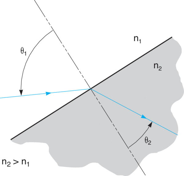
use Snell’s law to find θt
r = (ni-nt)/(ni + nt)
t = 2ni/(ni + nt)
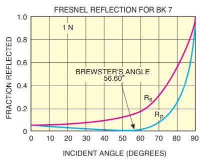
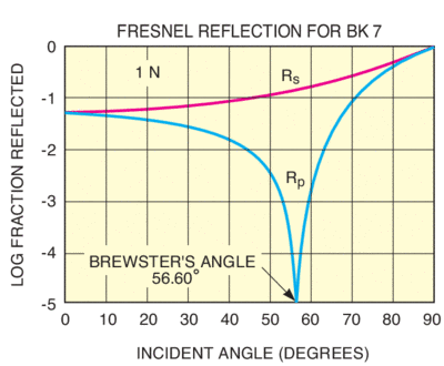
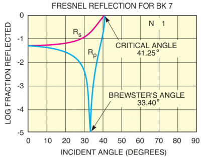
θβ = arctan (nt/ni)
Only s-polarized light reflected.
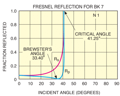
θTIR > arcsin (nt/ni)
nt < ni is required for TIR
The field reflection and transmission coefficients are given by:
r = Er/Ei t = Et/Ei
rs = (nicosθi -ntcosθt)/(nicosθi + ntcosθt)
rp = (ntcos θi -nicosθt)/ntcosθi + nicosθt)
ts = 2nicosθi/(nicosθi + ntcosθt)
tp = 2nicosθi/(ntcosθi + nicosθt)
The power reflection and transmission coefficients are denoted by capital letters:
R = r2 T = t2(ntcosθt)/(nicosθi)
The refractive indices account for the different light velocities in the two media; the cosine ratio corrects for the different cross sectional areas of the beams on the two sides of the boundary.
The intensities (watts/area) must also be corrected by this geometric obliquity factor:
It = T x Ii(cosθi/cosθt)
R + T = 1
This relation holds for p and s components individually and for total power.
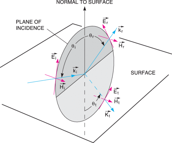
To simplify reflection and transmission calculations, the incident electric field is broken into two plane-polarized components. The “wheel” in the pictures below denotes plane of incidence. The normal to the surface and all propagation vectors (ki, kr, kt) lie in this plane.
 Over 8,000 products in-stock! & FREE 2-Day shipping on all web orders!* Learn More FREE T-Shirt with orders $250+ Details





 Ultra-High Velocity