Nonclassical Concave Grating Imaging
For nonclassical groove patterns, the aberration coefficients Fij must be generalized to account for the image-modifying effects of the variations in curvature and spacing of the grooves, as well as for the focusing effects of the concave substrate:
Fij = Mij + mλ/λ0 Hij = Mij + H'ij (7-18)
(p>The terms Mij are simply those Fij coefficients for classical concave grating mounts, discussed in Section 7.2 above. The H'ij coefficients describe how the groove pattern differs from that of a classical grating (for classical gratings, H'ij = 0 for all terms of order two or higher (i + j ≥ 2)). The tangential and sagittal focal distances (Eqs. (7-9) and (7-10)) must now be generalized:r'T(λ) = cos2β / A + Bcosβ + Ccosβ (7-19)
r'S(λ) = 1 / D + Ecosβ + Fsinβ (7-20)
where in addition to Eqs. (7-11) we have
C = – 2 H'20, F = – 2 H'02 (7-21)
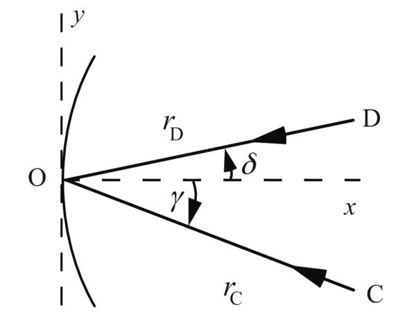
Here H'20 and H'02 are the terms that govern the effect of the groove pattern on the tangential and sagittal focusing. For a first generation holographic grating, for example, the Hij coefficients may be written in terms of the parameters of the recording geometry (see Figure 7-4):
H'20 = -T(rC, y) + T(rD, δ) (7-22)
H'02 = -S(rC, y) + S(rD, δ) (7-23)
where C(rC, ) and D(rD, ) are the plane polar coordinates of the recording points. These equations are quite similar to Eqs. (7-7) and (7-8), due to the similarity between Figures 7-4 and 7-2.
Nonclassical concave gratings are generally produced holographically, but for certain applications, they can be made by mechanical ruling as well, by changing the groove spacing from one groove to the next during ruling, by curving the grooves, or both. For such varied line-space (VLS) gratings, the terms Hij are written in terms of the groove spacing coefficients rather than in terms of recording coordinates.
Several important conclusions may be drawn from the formalism developed above for grating system imaging.
- The imaging effects of the shape of the grating substrate (manifest in the coefficients aij) and the groove pattern (manifest in the coefficients Hij) are completely separable.
- The imaging effects of the shape of the grating substrate are contained completely in terms that are formally identical to those for the identical mirrors substrate, except that the diffraction angle is given by the grating equation (Eq. (2-1)) rather than the law of reflection.
- The imaging effects of the groove pattern are dictated completely by the spacing and curvature of the grooves when projected onto the plane tangent to the grating surface at its center.
- The y-dependence of the groove pattern governs the local groove spacing, which in turn governs the tangential aberrations of the system.
- The z-dependence of the groove pattern governs the local groove curvature, which in turn governs the sagittal aberrations of the system.