Motion Basics Terminology & Standards
The function of a linear or rotary stage is to generate a desired motion in an ideal trajectory. Factors like friction between moving parts, quality of guides or bending induced by moving loads ,often deviate the motion from this ideal trajectory.
High performance motion systems are complex, so overlooking a seemingly small issue, either in design or in an application, can produce undesirable results. Thus, the intended use of a product along with the various measures of performance must be thoroughly reviewed. Unfortunately, many of the terms used by suppliers and users to characterize motion systems can mean different things to different people. In an effort to reduce confusion and misunderstanding, we will use terms and definitions as defined in globally recognized standards such as ISO 230-2 “Test code for machine tools —Part 2: Determination of accuracy and repeatability of positioning of numerically controlled axes” and ASME B5.54 “Methods for Performance Evaluation of Computer Numerically Controlled Machining Centers”.
When the terminologies in the referenced standards do not properly address a topic, we will use those common to the motion industry. The referenced standards served as a guide in the development of Newport test procedure.
Common Terminology Definitions
Abbe Offset: Instantaneous value of the perpendicular distance between the line where the displacement is measured and the line where the displacement is to be determined.
Abbe Error: Measurement error resulting from angular motion of a movable component and an Abbe offset.
Cross-coupling: In multi-axis systems cross-coupling refers to a change in one axis resulting from an input to another axis.
Functional Point: Point within the coordinate frame of the positioning system where a measurement and/or process is occurring.
Target Position: Position to which the functional point is programmed to move to.
Actual Position: Measured position reached by the functional point.
Position Deviation: Actual position reached by the functional point minus the target position.
Motion Control Coordinate System: In free space, an object is considered to have six degrees of freedom: three linear, along the x, y, and z-axes and three rotational around those (see Figure 1). All motions described here follow the right-hand coordinate system convention. The cross-product of +X and +Y axes (pointer and middle fingers) is the +Z axis (thumb). Also, if the thumb of the right hand points in the positive direction of an axis, the fingers will wrap around the axis in the direction of positive rotation about that axis. All movements are composed of translations along and/or rotations about the coordinate axes. Generally, the X and Y axes are on the horizontal plane, the direction of travel of the first or bottom stage is aligned with the X axis, and the Z-axis is vertical. For parallel kinematic systems, cardan angles are used.
Resolution: Resolution, also referred to as display or encoder resolution, is the smallest increment that a motion system can be commanded to move and/or detect. It is not the same as Minimum Incremental Motion. A system may or may not be able to consistently make incremental moves equal to the resolution. Factors that can affect a move include friction, load, external forces, system dynamics, controller, vibrations, and inertia.
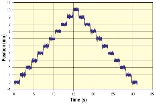
Minimum Incremental Motion: Minimum Incremental Motion (MIM) is the smallest increment of motion a device is capable of consistently and reliably delivering. It should not be confused with resolution, which is typically based on the smallest controller display value or smallest encoder increment. Resolution can be significantly smaller than the smallest actual motion output, a key distinction, but unfortunately not always well understood. Newport specifies the minimum incremental motion with most of its products. Others refer to it as "practical resolution". Two different test methods are used depending on the capabilities of the stage. In high performance stages that use direct drives and frictionless guiding systems, the MIM is only limited by noise.
Accuracy: Accuracy is a measure of the degree to which a given displacement conforms to an agreed upon standard. The accuracy of a motion system can be highly influenced by the test set up, environmental conditions and the procedure used to measure displacement. In the micron and submicron world, thermal expansion can have a profound impact upon accuracy, particularly when temperatures are not constant or well controlled. Other common parameters that adversely affect accuracy include cosine and Abbe errors. In multi-axis systems undesired motion in any direction produces additional uncertainty.
With the majority of modern controllers, linear error compensation can be easily accomplished by entering a compensation factor into the controller. Newport specifies Accuracy after compensation and provides a control report indicating the compensation value with every stage.
Repeatability: Repeatability is a measure of the positioning system’s ability to sequentially position. It can be unidirectional (when approaching target position always from the same direction) or bidirectional (when approaching the target position from either direction). In a number of applications, the repeatability of a motion system is more important than the accuracy. Systematic errors can be taken into account and compensated, but the repeatability is the ultimate limit that is reached after all compensation.
Note: In most cases Newport specifies both uni-directional and bi-directional repeatability for motion devices. Sometimes, when reversal error is very low, we only specify bi-directional repeatability.
Reversal Error: Reversal error is the distance between actual positions reached for a given target position, when approached from opposite directions. This value is a combination of backlash and hysteresis.
Backlash: Backlash is the result of relative movement between interacting mechanical parts of a drive system that does not produce output motion. Contributing factors include clearance between mechanical parts such as gear teeth and mechanical deformation. Not all systems have backlash and when they do, it mainly affects bi-directional repeatability. Backlash can be compensated by motion controllers due to its repeatable nature.
Hysteresis: Hysteresis is a component of reversal value that is dependent on the recent history of the system. It is the result of elastic forces in the various components and is observed, when the forces acting on a system reverse direction. Hysteresis affects both bi-directional repeatability and accuracy. It also affects precision alignment and position tracking applications as the output motion is not linear to the input motion, when reversing the direction of the motion. Unlike backlash, hysteresis is present in all mechanical systems although its value may be low.
Runout of a Linear Stage – Straightness / Flatness: Runout is the departure of the moving functional point from the desired ideal straight line motion. It consists of two orthogonal components. In ISO-230 and ASME B5.57 standards, runout is referred to as straightness. However, it is common in the motion industry to refer to it as flatness and straightness. Flatness is the runout in the vertical plane and straightness is the runout in the horizontal plane (see Figure 4).
Angular Runout of a Linear Stage – Pitch / Yaw / Roll: Angular runout is the rotation of the moving functional point. It has three orthogonal components commonly referred to as pitch, roll, and yaw. Assuming a linear stage with a horizontal carriage moving along X, pitch is the rotation around the Y axis, yaw is the rotation around the Z axis and roll is the rotation around the X axis (see Figure 5). A precise assessment of the runout errors for a given application can be complex, especially with multi-axis systems or with applications where the relevant reference point is at a long distance from the stage bearings. In such cases, the linear off axis errors introduced by the angular deviations of the stage and amplified by the distance are the main components of runout (Abbe Errors).
Eccentricity of a Rotary Stage: Eccentricity is the radial (perpendicular to the axis of rotation) deviation of the center of rotation from its mean position as the stage rotates through one revolution (Figure 6). It is also referred to as radial runout. A perfectly centered stage with perfect bearings would have no eccentricity.
Wobble of a Rotary Stage: Wobble is the tilt of the axis of rotation relative to the ideal axis, over one revolution (ref. Figure 6). It is most easily observed as a cyclic tilting of the rotating surface or table top of a stage and can produce Abbe error. Like eccentricity, it is generally the result of imperfect bearings.
Position Stability: Position stability is the ability to maintain a position within a specified position range over a specified time interval. It is the sum of drift and vibrations.
Drift: Drift is the slow deviation from a stable position. It mainly depends on the migration of lubricants and thermal variations.
Vibrations: Vibrations (in position noise) are fast alternative motions of small amplitude generated by the environment (noise from the flow, air fans) and electronics (motor driver).
Load Capacity – Centered / Transverse / Axial: Load Capacity is the maximum allowable force that can be applied to a stage in a specified direction while meeting stage specifications. This maximum force includes static (mass * gravity) and dynamic forces (mass * acceleration). Dynamic forces must include any external forces such as vibrations acting upon the stage. The amount of acceleration a stage can impart to a mass is limited to the accelerating force it can produce without exceeding the load capacity. The torque induced by a load not centered on the carriage can be a significant factor to consider when cantilevered loads are accelerated with linear stages.
Centered Normal Load Capacity: For linear stages, this is the maximum load that can be applied to a stage, with the load center of mass at the center of the carriage, in a direction perpendicular to the axis of motion and the carriage surface (see Figure 7). For rotary stages, it is the maximum load along the axis of rotation. In addition, the rotational moment of inertia must be within limits for rotary stages.
Transverse Load Capacity: Also called side load capacity, is the maximum load that can be applied perpendicular to the axis of motion and along the carriage surface (see Figure 7). This is typically smaller than the normal load capacity.
Axial Load Capacity: Axial Load Capacity is the maximum load along the direction of the drive train (see Figure 7). For linear stages mounted vertically, the specified vertical load capacity is usually limited by the axial load capacity. However, cantilevered loading must also be considered.
Back Drivability: With reversible driving system a force applied to the stage carriage can generate motion, when its motor is not powered. Such stages are called back drivable. Stages with direct drives are back-drivable with a low force: Stages with ball-screw are back-drivable, if the applied force is above a given threshold depending on the ball screw characteristics.
Stages with lead-screw are generally not back-drivable, unless pitch of the screw is very high. If the stage is back drivable and used in vertical applications, a payload-dependent force is constantly applied, resulting in downward motion of the stage carriage at power off. Unless otherwise specified, the back-drivability threshold of Newport stages is above the Axial Load Capacity.
Off-Center Load Capacity: The maximum load capacity of a stage is diminished when the load is not centered (refer to the stage specifications section in the catalog for off centered load equations and/or contact Newport’s Applications Engineers to discuss your specific load conditions).
Maximum Inertia: Inertia is the measure of load’s resistance to change in velocity. The larger the inertia, the greater the force required to accelerate or decelerate the load. If there is a constraint on the amount of force available, then the allowable acceleration and deceleration must be adjusted to an acceptable value. Inertia is a product of mass elements and the square of their distance from the axis of rotation. The maximum inertia specified for rotary stage is a value based on available torque (limitation in acceleration) and bearing stiffness (limitation in natural frequency and associated vibrations).
Speed (Velocity): Speed (Velocity) is the rate of change of position. The maximum speed specification is provided at the stage’s normal load capacity. Higher speeds are possible for lower loads or larger motor drivers. Minimum speeds are highly dependent on a motion system's speed stability.
Speed Stability: Speed stability is a measure of the ability of a motion system to maintain a constant speed within specified limits. It is usually specified as a percentage of the desired speed. Also specified as velocity regulation, this parameter depends upon the stage’s mechanical design, its feedback mechanism, the motion controller, control algorithm, the magnitude of the speed, and the application.
The actual speed of a moving part is usually not measured directly. Instead, it is calculated based on a sample of the position. As a result, the value of speed stability depends a lot on the sampling frequency. In order to be accurately defined, speed stability should be specified in a given bandwidth.
Acceleration: Acceleration is the rate of change of velocity. Unless otherwise specified, Newport sets the acceleration of its stages to a value that enables the stage to reach the maximum velocity in 250 ms, so maximum acceleration = maximum speed * 4/s.
Jerk: Jerk is the rate of change of acceleration.
Mean Time before Failure: Mean Time before Failure (MTBF) is the prediction of product reliability. Tests and statistical analysis of parts and components are performed to predict the rate at which a product will fail. It is one of the most common forms of reliability prediction and is usually based on an established analytical model. Many models exist, and choosing one over another must be based on a broad array of factors specific to a product and its application. In general, MTBF is specified with a duty cycle parameter.
In the case of simple system with a constant failure rate (number of failures/unit time), the fraction of units still working after a time equal to the MTBF is 37%.
ESP Auto-configuration

The nonvolatile memory of Newport stages are preprogrammed with unique information such as stage electrical characteristics, motor and encoder type, lead screw pitch, maximum velocity , maximum acceleration, etc. Once connected to the motion controller, the stage is recognized and its parameters are uploaded to the driver. This is Newport's exclusive ESP (Enhanced System Performance) technology that allows true plug-and-play compatibility for a quick and safe start of positioning applications.
Metrology Capabilities & Standards
Our Promise
In our continuing effort to provide the most accurate information to research, defense & homeland security and industrial communities, we have expanded many of our product specifications to reflect the true performance users can expect. We refer to these as "guaranteed" and "typical" specifications. This document provides a thorough discussion of what "guaranteed" and "typical" specifications mean as well as how they are derived and verified. Knowing how specifications are derived can give a better understanding of the true performance of a motion product than simple numerical values. This eliminates the mysteries in "specmanship" and allows the user to select the best solution for their application.
This is our promise!
Newport's Guaranteed Specification
Although not explicitly stated in the past, our motion products have always been introduced only after their production specifications were guaranteed. The Guaranteed Specifications are the worst-case values that users can expect for a particular product, tested per Newport Metrology Procedure following ASME B5.57 and ISO 230-2 standards. Any motion product that is outside of these guaranteed specifications is either re-worked until it meets them or scrapped, if there is no other option to meet the published specifications.
Newport's Typical Specification
Typical Specifications have been provided for our most popular motorized products and are based upon initial or ongoing statistical production results. Typical values can be considered to be the mean performance values for a particular specification. For some motorized stages the statistical test data is presented. This specification provides the users with more realistic description of the performance for a particular stage family.
Metrology Standards
For almost 50 years Newport Resource has been the reference standard used by researchers, scientists and engineers to advance their technologies, discoveries and products. In today's world of shrinking feature sizes, nanometer-scale devices, as well as higher accuracy and resolution requirements, it is critical to use the highest quality components available. This is why Newport provides testing and test data for on-axis accuracy, repeatability and trajectory errors (e.g. Pitch and Yaw for linear stages and Wobble and Eccentricity for rotation stages) with every XM, GTS, IMS, IDL, ILS, MTN, UTS, MFA, VP, RGV, RV, URS, PR/SR, LTA and TRA motion product.
The final performance of a positioner depends on many factors in the manufacturing process (precision of machined parts, tolerances in the assembly, etc.) A rigorous quality control and metrology procedure is the only way to guarantee that a stage or actuator meets its published specifications.
Newport's internal metrology procedure is a very comprehensive combination of other widely known procedures including ASME B5.57 and ISO 230-2.
Newport is part of a metrology standards project in collaboration with the National Institute of Standards and Technology to better address the specifications of High performance motion systems. Refer to "Methods for Performance Evaluation of Single Axis Positioning Systems: A New Standard".
Below is a list of the major aspects of Newport's test procedures that assure our customers receive only the highest quality products.
General Information
- All test tools are mounted on the center of the carriage at a height of approx. 50 mm to closely mimic typical applications. Repeatability, reversal value, and accuracy for linear stages are measured in comparison to a calibrated laser interferometer.
Repeatability, reversal value, and accuracy for rotary stages are measured in comparison to high accuracy rotary encoder that is coupled to the rotating platen of the stage.
- Newport's dedicated metrology room is temperature controlled. All the stages to be tested are stored in the room for stabilization before the actual measurements are taken. A certified third party metrology institute provides regular calibration of the test tools to guarantee the highest precision possible.
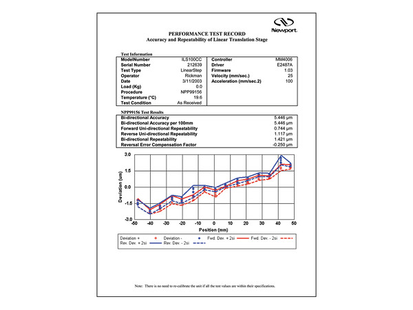
- Test reports verifying performance of every motion product (as shown in Figure 9) are supplied at NO ADDITIONAL COST to our customers. These test reports not only verify the performance of our products, but also provide sufficient detail to allow users to improve the performance of their positioning products through backlash compensation, error mapping or linear compensation.
Indexing Measurement
- Controlled test bench data taken at 21 measurement points throughout the full travel range of the stage. This high number of measurement points ensures careful identification of the stageÕs characteristics along its entire travel range. A typical positioner may perform very well along specific points over travel range, but might have significantly different characteristics at other points due to imperfections in the bearings or drive screw. Procedures that collect only a few data points (4 or 5 for example) do not accurately represent the true performance of the positioner and may not truly meet published specifications along the full travel range.
- Controlled test bench data taken in both directions for 4 complete cycles of motion. This element is not only essential to verifying the repeatability and reversal errors of the positioner, but also provides more precise qualification of positional accuracy. This type of test also confirms that the characteristics of the positioner are consistent and eliminates any "lucky" test results. This test provides 168 points of data that are used to determine the positioner's true performance. The statistical methods used to evaluate this data are presented in Figure 10.
- Accuracy is specified as a peak to peak deviation. The linear part of the deviation is compensated by using the true value of the encoder increment in the control system. This true value is provided together with every positioner control report.
- Uni-directional repeatability is specified at a factor of 3 standard deviations (+/- 1.5 sigma). The standard deviation is calculated from the positioning data taken at all 21 measurement points in the forward and reverse directions. With 4 cycles of motion, this makes a total of 168 data points. The high number of data points and the 3-sigma approach provides a very accurate indication of the worst-case repeatability with 86% certainty. This means when moving to the same position hundreds of times, 86% of the moves will be repeatable within the specified span.
- Bi-directional repeatability includes reversal error. It is defined as the sum of the Uni-directional repeatability and the reversal value: Bi-directional repeatability = Uni-directional repeatability ± Reversal error / 2.
- Bi-directional repeatability with compensation indicates that the control system is set with the reversal error found in the provided control report.
- NOTE: It is important to clarify that Newport specifies repeatability of positioning products as 3- sigma value, unlike some companies that an RMS (Root Mean Square) or mean repeatability to make their data look more impressive. RMS or "mean" repeatability is the expected repeatability error, when moving to the same position many times. It converts to 1-sigma specification certainty. So 0.5 µm RMS (or 1-sigma) repeatability is the equivalent of a ±0.75 µm repeatability specified by Newport's A167 procedure.
Linear/Rotational Error Measurements
- 100 data points are taken for pitch and yaw of linear stages using Newport LDS autocollimator. These data points are taken dynamically, on the fly, along the travel. The performance specification presented in the test report is the true magnitude of the error (the difference between the max and min error).
- 100 data points are taken dynamically for wobble and eccentricity of rotation stages using a Newport LDS autocollimator. These values are measured during 2 full rotations. Taking data during one rotation only will not detect all the runout errors as the bearings rotate at only half the speed of the stage. The deviations are measured along two orthogonal axes and combined to get the full vector. Data is processed to remove the error coming from the alignment of the measuring sensor, so the control reports display the true error of the positioner. The numerical value is defined as a sum of error mean value and error standard deviation .
Minimum Incremental Motion Measurements
There are no standard tests to quantify the minimum incremental move positioning axis can achieve. An effort has been launched by members of US government, industry, and academia to develop a new positioning standard [Brian OÕConnor, Ronnie Fesperman, and Serge Maneuf, Methods for Performance Evaluation of Single Axis Positioning Systems: Incremental Step, Proceedings of the ASPE Annual Meeting, 2013.], but it is not yet a standard. Thus, Newport has developed its own internal method and standard for characterizing MIM.
- A number of small incremental moves are commanded in forward and reverse directions. The actual displacement with each step is measured with an external tool (for example laser interferometer).
- A pass-fail criteria is defined: 3 times the standard deviation of the actual displacement must be smaller than the commanded step size.
- The Minimum Incremental Motion is the smallest step size for which the criteria is satisfied. This ensures that an individual step will result in a real displacement within a certain tolerance.
Summary
The old practice of evaluating products based solely upon product catalog specifications, such as repeatability, accuracy, pitch, roll, and yaw, supplied by the manufacturer can be a very risky way to choose a product, especially in the submicron and nanometer performance range. In today's ultra-high precision environment, it is imperative to have a clear understanding of the origin of motion control specifications. Knowing how they are derived can be ultimately more telling than the numerical value itself.
Upon request, Newport will supply historical test data for most of its motorized positioners. For more information on Motion Control specifications and technology, please review our Motion Control Tutorial and Application Notes, or contact your local Newport Applications Engineer.