Measurement of Instrumental Stray Light
The consequence of undesired energy reaching the detector in a spectrometer is a reduction in photometric accuracy, since some light reaches the detector that cannot be attributed to the transmission (or absorption) of the sample at the analytical wavelength. Instrumental stray light, like scattered light, is generally measured either with cut-off filters or monochromatic light.
The Use of Cut-off Filters
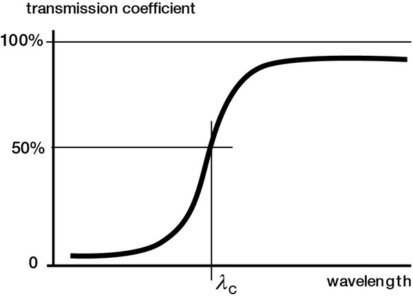
Instrumental stray light is commonly measured by using a set of high-pass cut-off optical filters (whose transmission curves look like that in Figure 11-10). The spectrometer is then scanned toward shorter wavelengths and the transmittance measured; once the transmittance level has reached a steady minimum (a plateau), this reading is taken to be the stray light.
The instrument is tuned to the analytical wavelength λ and a series of filters, each with a successively higher cut-off wavelength λC (>λ), is placed in the beam and intensity readings taken at the detector. [Generally, λC should exceed λ by at least 20 nm, in the visible spectrum, to ensure than virtually no light of the analytical wavelength λ passes through the filter and complicates the readings.] Nonzero readings indicate the presence of stray light. A proper study requires measurements at more than one analytical wavelength since stray light properties cannot be easily extrapolated (due to the different wavelength dependencies of the causes of grating scatter and instrumental stray light noted above, and – for monochromators – the fact that all rays diffracted from or scattered by the grating change direction as the grating is rotated).
The Use of Monochromatic Light
Another method for measuring instrumental stray light is to replace the polychromatic light source (used with cut-off filters) with a narrow-band monochromatic light source. Atomic emission sources provide narrow spectral emission lines that can be used for this purpose; lasers can be used; and broad-spectrum sources can be used in conjunction with bandpass filters.
Kaye describes a technique in which monochromatic light is used to determine the amount of power detected at all wavelength settings for a given input wavelength; this quantity is called the slit function. The spectrometer (with slit widths w) is illuminated by light whose central wavelength is λ, and whose spectral width Δλ is very narrow (Δλ <<λ). Scanning through the full wavelength range of the instrument (the wavelength setting being denoted by λ ; see Section 10.1.6) and recording the power at each setting yields the slit function Sλ(λ,w), which we may write as
Sλ(λ,w) = cEλMλ(λ,w)Rλ (11-4)
where Eλ is the power emitted by the source, Mλ(λ,w) is the transmittance of the optical system (between the source and the detector), Rλ is the sensitivity of the detector, and c is a constant of proportionality. If we had knowledge of the slit function for all input wavelengths λ and for all wavelength settings λ, we would be able to write for any wavelength setting the following integral:
S(λ,w) = 0∫∞Sλ(λ,w) (11-5)
which represents the total power (for all wavelengths) recorded at wavelength setting λ. In practice, the bounds of integration are not 0 and ∞, but are instead determined by the spectral sensitivity limits of the detector.
Stray light can then be expressed as the ratio of the intensities (powers) of the scattered light and principal beam.
Signal-to-noise and errors in absorbance readings
Often the unwanted light in a spectrometer is quantified not by instrumental stray light but by the signal-to-noise ratio (SNR), a dimensionless quantity of more relevance to instrumental specification.
The SNR is defined as the ratio of the signal (the desired power incident on the detector) to the noise (the undesired power, equivalent in our definition to the instrumental stray light).
Another specification of instrumental stray light is given in absorbance, a dimensionless quantity defined by
A = log10(100/T) (11-6)
where T is the percent transmittance (0 ≤ T ≤ 100). Higher values of A correspond to lower transmittances, and instrumental stray light plays an important role in the highest value of A for which the readings are accurate; an instrument for which the stray light is about 1% as intense as the signal at a given wavelength cannot provide absorbance readings of any accuracy greater than A ≈ 2.
When the stray light power s is known (as a percentage of the signal), Eq. (11-6) may be modified to be made more accurate:
A = log10((100-s)/(T-s)) (11-7)