Instability Oscillation of High CG Table Systems
Table stability can cause problems for customers with high “Center of Gravity” systems. This occurs in applications with thick optical tables and/or narrow table widths. Use of high CG equipment such as table enclosures and SEMs can also cause instability. Below is a description of stability problems and an applications checklist.
There are two types of rocking or hunting motions to which pneumatic isolator supported optical tables systems are susceptible. The first type is simple static instability caused by a high CG payload combined with a narrow isolator spacing; the table lurches, tilting from one side to the other, pauses, and then lurches back and forth again repeatedly in a jerking sort of motion. The second type is a dynamic or leveling control-oscillation. In this case, the table rocks quickly from side to side at about 2 Hz and the valves hiss significantly. The causes and cures for these two problems are different, but the symptoms are similar enough to cause misdiagnosis's
Static Instability
Table systems rock about the “roll center” midway between the narrowest spaced isolators at the height of the isolator diaphragms. Because the CG of most isolated systems is above the height of the diaphragms, the CG moves from side to side when the payload tilts. As the payload CG moves horizontally away from the roll center, the weight of the payload actually causes the payload to tilt more. This tendency to tilt more is counteracted by the stiffness of the isolators. In engineering terms, the system is statically stable as long as the righting moment is greater than the overturning moment.
Given as:
[Isolator stiffness x 1/2 isolator spacing] > [Payload CG shift x payload weight]
Note that the stiffer the isolators are, the better the system stability is. Unfortunately, stiffer isolators do not isolate as well as softer isolators, so a design trade-off must be made.
For a given tilt angle, a higher CG changes position more than a lower CG. As a result, static instability occurs when the higher (payload CG shift x payload weight) product exceeds the righting moment for high CG systems. For the typical pneumatic isolator system, the critical CG height is about half the narrowest distance between isolators above the isolator diaphragms. This rule of thumb is illustrated next.
Static stability is independent of the leveling valves, their adjustment or the air pressure as long as there is enough pressure to float the system. To confirm that a system is statically unstable, stabilize the system by hand and close the needle valves on the three leveling valves all the way. Let go of the system. If it tilts to one side and stays there, it is statically unstable.
The important thing to note is that even though some systems are more statically unstable than others, no unstable system will provide high performance isolation.
Cures for Static Instability
There are only two effective cures for static instability. Either the CG height above the roll center must be reduced or the isolator spacing must be increased. The CG height can be reduced by using a thinner table, outriggers or leg pockets.
In some cases, ballast can be added to the bottom of the table to lower the total payload CG. The ballast must be supported by through inserts to avoid delaminating the bottom table skin. The easiest way to increase isolator spacing is to specify a wider table. Outriggers both increase isolator spacing and lower the CG, but take up lab space without increasing usable table area. Leg pockets lower the CG. They are very effective in thicker tables.
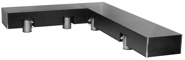
Stability of marginally stable tables can be improved by moving the isolators closer to the table edges. The standard isolator location is six inches in from the table edges. The isolator top plates are eight inches in diameter, so the isolators can be moved two inches further outward. If this is done, the isolator bodies will extend one inch beyond the table edge. In addition, it is necessary to drill and tap new isolator clamp holes to secure the isolators in place for earthquake safety.
Another way to improve stability of narrow systems is to slave the isolators on the long side of the table together. In the standard plumbing configuration, the isolators at one end of the table are slaved together. As the table rolls, these isolators simply trade air back and forth and do not provide a righting moment. In a four isolator standard system only two isolators contribute to roll stability. By slaving the isolators on the long side together, all of the isolators contribute to making the system more roll stable. The downside of this approach is that the system may be more difficult to level due to the greater spacing of the slave legs and longitudinal stability will be reduced.
Static instability can be masked by using a very efficient leveling system to prevent large amplitude rolling. In this case, the table will oscillate with very low amplitude within the leveling valve dead band. Isolation at low frequencies is severely impacted.
Active isolation systems which use a pneumatic isolator to support the payload weight are subject to many of the same static stability limitations as standard pneumatic systems. Soft steel spring supported systems may be less susceptible to static instability if the spring is significantly stiffer than a pneumatic isolator. Stability of active isolation systems which incorporate a relatively stiff elastomeric spring, such as the Elite™ 3, is generally far superior to that of pneumatic systems. This makes Elite type systems more suitable for high CG and changing load applications.
Problem Table Sizes
Static stability problems are most common in 2 ft and thicker table systems. For example, the CG of a 2 ft thick table is 12 in. above the table bottom and about 15 in. above the isolator diaphragms. The isolator spacing of a 4 ft wide table is 36 in. The acceptable CG height is then about 18 in. Even a light customer load may raise the system CG high enough to make the system statically unstable. Each table system with a width-to-thickness ratio less than about 2.5 should be checked for stability.
Dynamic Instability
The leveling valves are the controllers in a pneumatic positioning servo system and control table height. The valves feedback table height by inletting or exhausting air to or from the isolators as required to maintain the desired height. If the air is inlet or exhausted too fast, the system will oscillate.
Cures for Dynamic Instability
The easiest cure for dynamic instability is to reduce the airflow. Adjust the supply air pressure until it is about two to ten psi higher than is necessary to float the system. Set the needle valves per the isolator manual. If the system still oscillates, reduce the air pressure and close the needle valves incrementally until the oscillation stops.
There is interaction between static and dynamic instability. Systems that are marginally stable statically will be the most difficult to stabilize dynamically.
Special Applications
An ever increasing number of OEM applications demand faster releveling and settling times and better leveling accuracy for isolation systems used with automated precision inspection systems. For these applications, special valves with higher airflow and special isolators with higher damping are used. Simply changing the leveling valves will not improve releveling times or improve stability.
Newport’s standard isolators are designed with damping suitable for a wide range of applications. For special applications, custom damping can be installed in all Newport isolators. Higher damping adversely affects isolation but permits higher airflow and reduced leveling and settling times. Each application is different and experimentation may be required to achieve the best results.
Leveling accuracy is largely independent of system stability issues. Precision leveling valves must be selected based on both the leveling accuracy and the releveling and settling time requirements.
Pre-Design Stability/Troubleshooting Checklist
- Is the system statically stable?
- Is the air pressure correct?
- Are the needle valves adjusted correctly?
- How does the system respond to changing or moving customer loads?
Summary
Pneumatic isolation systems are suitable for most applications with invariant loads. Care in specifying and designing the isolation systems will ensure stable operation. However, there are an increasing number of applications that are at the limits of pneumatic system performance and require careful engineering if they are to perform to customer expectations. In the future, active isolation systems will meet requirements that are more stringent