How to Build a Beam Expander
Beam expansion or reduction is a common application requirement in most labs using lasers or light sources and optics. There are many ready-made beam expanders available on the market, but often they are not available in the required expansion ratio or spectral range. And, for students or those working within a tight budget, the plug and play solution may not be the answer.
Luckily, building a beam expander from off-the-shelf components is easily accomplished and can fit into most budgets. The quality of the output is dependent only on the input beam and the component optics used.
To create a beam expansion unit, it is important to know a few simple optical relationships, as well as what your input to output beam diameter ratio requirement is.
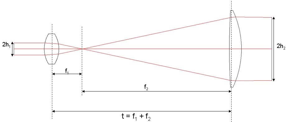
Simple beam expanders, sometimes referred to as telescopes, in their most basic forms generally consist of two lenses. The first lens should have a diameter larger than the maximum expected input diameter of the incoming light source. For example, if the diameter of the incoming beam is 10 mm, a 12 mm diameter lens will do a nice job with a little room to spare. The input beam is assumed to be collimated.
The diameter of the output lens should be larger than the desired exit beam diameter. For a 3x expansion ratio with a 10 mm maximum input beam diameter, an output lens of greater than 30mm in diameter is required. The useable diameter of a lens is usually specified at 90% of the actual lens diameter, a minimum lens diameter of 33.3 mm would be required. If you are using off-the-shelf lenses, this will translate to 38-50.8 mm in diameter.
The magnification of a 2-lens system is equal to the ratio of the focal lengths of the lenses, which is also equal to the ratio of the radii of curvatures of the lenses.
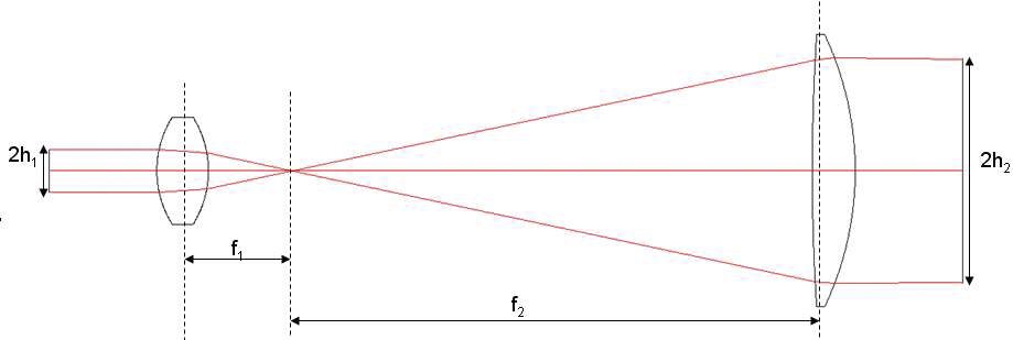
M = f2/f1= R2/R1 = h2/h1
where,
M = the magnification of the beam expander
f2 = effective focal length of exit lens
f1 = effective focal length of entry lens
R2 = radius of curvature of exit lens
R1 = radius of curvature of entry lens
h2 = radius of exit spot (image height)
h1 = radius of entry spot (object height)
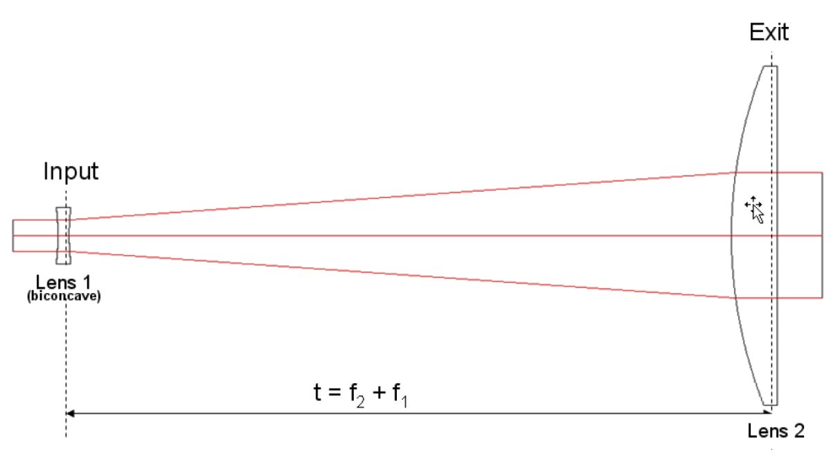
The spacing, t, between the two lenses will be equal to the sum of the focal length of the lenses.
t = f1 + f2
A beam expander can be used in reverse, with the larger diameter lens as the input and the smaller diameter lens as the output, in order to reduce the diameter of the input beam.
Keplerian Beam Expander
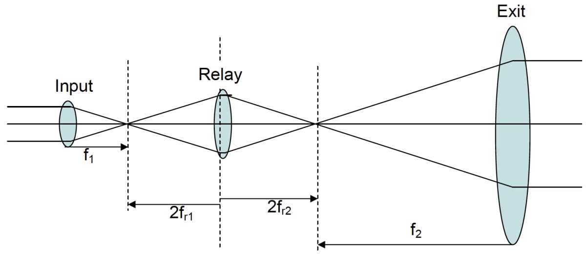
The easiest beam expander to build is a Keplerian Telescope. In the Keplerian model the focal lengths of both lenses will be positive, their addition resulting in a focal point in the gap between the lenses at the point where the two focal lengths meet. Because there is a high power density due to the focused spot size at the focal point between the lenses, Keplerian beam expanders are not recommended for use with lasers with high pulse energies. This is because the high pulse energy density at the focal point can cause the air to arc. However, if you would like to clean up the beam as it passes through the beam expander, this focal point can be a handy place to position a pinhole. It will be necessary to make certain that the energy density of the beam at the focal point does not exceed the damage threshold limitation of the pinhole material. Also, in imaging applications, because the image will be inverted and reverted at the output, the addition of a third lens (relay lens) may be required to correct the image orientation.
In this example, the simplest version of a relay lens would be a biconvex lens inserted between the input and output lenses of the beam expander, such that distance between the input lens and the relay lens is:
tr1 = f1 + 2fr1
and the distance between the relay lens and the output lens is
tr2 = 2fr2 + f2
Where, fr1 and fr2 are the relay lens focal lengths.
The overall length of the beam expander will be increased by the sum of the focal lengths of the relay lens.
The magnification of this modified beam expander will be equal to the product of the magnification of the relay lens and the magnification of the original Keplerian telescope.
Msystem = (MKeplerian) (Mrelay)
where,
MKeplerian = f2/f1 = magnification of Keplerian beam expander
Mrelay = fr1/fr2 = magnification of relay lens
If the desire is to preserve the magnification of the original beam expander before insertion of the relay lens, the ratio of the focal lengths of the relay lens should be unity in order to have relay lens magnification of 1.
Galilean Beam Expander
A simple Galilean telescope also consists of 2 lenses, one with a positive focal length and one with a negative focal length. Because of the difference in signs of the focal length, there is no focal point between the lenses and the distance between the lenses is shorter than in the Keplerian model. This shorter distance allows for a more compact design. The output image will also be erect and will not require a correction lens.
The Magnification of the Galilean system is given as
M = - f2/f1
where,
f1 = focal length of lens 1 and is a negative value (input lens)
f2 = focal length of lens 2 (exit lens)
It is important to choose the proper lens shape, substrate material, and anti-reflection coating for your application.
Plano-convex/concave lenses would typically be used to minimize spherical aberrations when the input and exit beams are collimated and the lenses are oriented with the curved surfaces facing the collimated beams. Bi-convex/concave lenses would typically be used to minimize aberration if the entering and exiting beams were diverging.
For beam expander applications where incoming and outgoing beams are collimated, the input and exit lenses will each introduce some aberration. The total aberration of the system may be minimized by choosing a planar or symmetrical input lens to balance the aberration of the exit lens in normal or reverse orientation.
The tables below show a few sample configurations for common beam expansion ratios for both the Keplerian and Galilean two lens models. The lenses in the table are uncoated. Please check Newport website for anti-refection coated versions for your light source. These are by no means the only possible configurations.
The appendix at the end of the paper shows how simple it is to construct an off-the-shelf beam expander in Zemax, along with analysis data.
Keplerian Beam Expander Samples
| M (approx) |
Lens 1 | Diameter (mm) |
Effective Focal Length (mm) |
Lens 2 | Diameter (mm) |
Effective Focal Length (mm) |
Max Input Beam Diameter (mm) |
|---|---|---|---|---|---|---|---|
| 2X | KBX022 | 12.7 | 12.7 | KPX076 | 25.4 | 25.4 | 10 |
| 3X | KBX028 | 12.7 | 25.4 | KPX181 | 50.8 | 75.6 | 10 |
| 4X | KBX028 | 12.7 | 25.4 | KPX187 | 50.8 | 100 | 10 |
| 6X | KBX028 | 12.7 | 25.4 | KPX226 | 76.2 | 150 | 10 |
Gallilean Beam Expander Samples
| M (approx) |
Lens 1 | Diameter (mm) |
Effective Focal Length (mm) |
Lens 2 | Diameter (mm) |
Effective Focal Length (mm) |
Max Input Beam Diameter (mm) |
|---|---|---|---|---|---|---|---|
| 2X | KBC028 | 12.7 | -12.5 | KPX076 | 25.4 | 25.4 | 10 |
| 4X | KBC013 | 6.35 | -6.3 | KPX076 | 25.4 | 25.4 | 5 |
| 8X | KBC028 | 12.7 | -12.5 | KPX229 | 76.2 | 200 | 10 |
Appendix
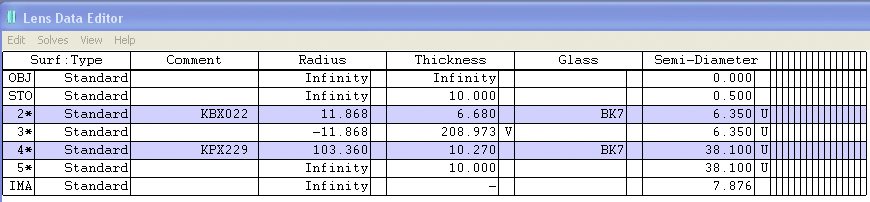
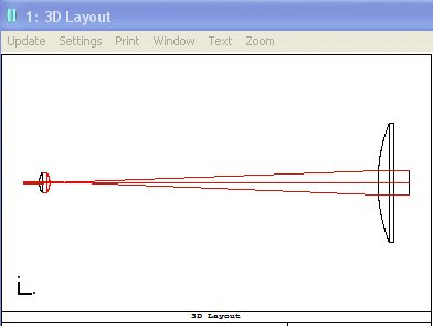
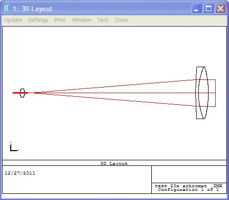
The following is a Zemax example for a 16X KIeplerian beam expander using BK7 lenses already loaded into the Lens Catalog (F5) for Newport Corporation. We make the assumption that the reader has some experience with Zemax. The following is not intended as a tutorial in how to use a lens design program.
Begin with a blank Lens Data Editor with the Stop set to surface 1. Enter the KBX022 biconvex, 12.7 mm diameter, 12.7 mm focal length lens onto surface 2 using the Lens Catalog. This is the entry lens for the beam expander.
Enter KPX229 plano-convex, 76.2 mm diameter, 200mm focal length lens into surface 4 using the Lens Catalog.
Set the distance between the two lenses to be variable.
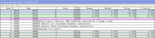
In the Merit Function Editor, enter the effective focal length, EFLY, for each lens. Take the ratio of the focal lengths using the DIVI command.
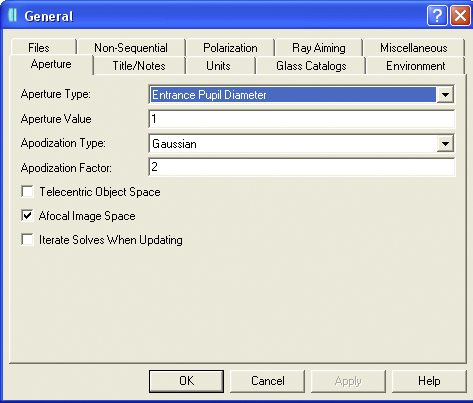
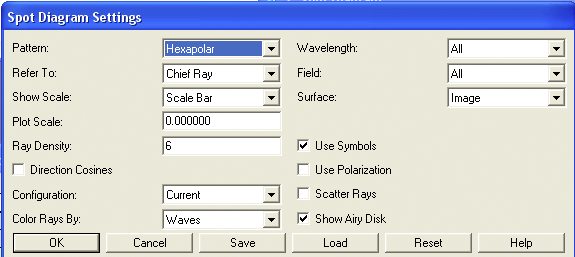
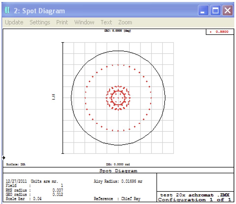
In the General settings window under the System menu, set the Aperture Type to Entrance Pupil Diameter The Aperture Value to 1 mm, the Apodization Type to Gaussian, the Apodization Factor to 2, and check the Afocal Image Space option. In the Spot Diagram Settings window set Pattern to Hexapolar. Choose to show the Airy disk.
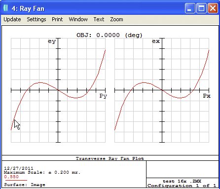
After updating, doing a short automatic optimization, and updating again, you should see the following results. Note that we have optimized this configuration for one wavelength only, 550nm. The distance between the lenses will change slightly depending on the wavelength used. This is due to the variation in focal lengths throughout the acceptable spectral range of the lens materials and coatings as you move away from the design wavelength(s). The Spot Diagram shows a near diffraction limited result.
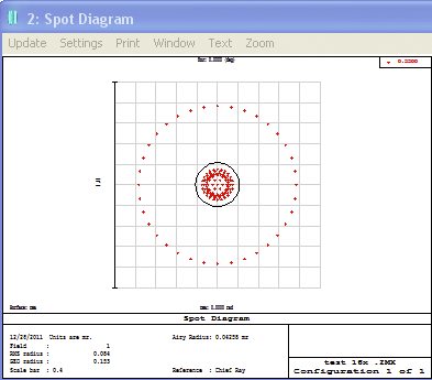
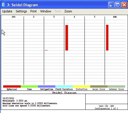
The major aberration contribution is from spherical aberrations, though this is slight as seen from the Seidel Diagram, with an overall value of approximately 0.00425 mm. And looking at the Ray Fan Diagrams, we can see that the spherical aberrations are well balanced.
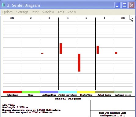
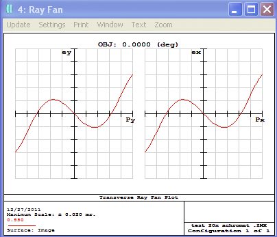
Using a bi-convex or achromatic lens can bring the spot diagram closer to or well within the diffraction limit of the system. As can be seen for the 20X Keplerian system below which uses the PAC095 achromatic lens for the exit lens. Here the RMS radius value is well enclosed by the Airy disc and the beam expander system is definitely diffraction limited.
Again, the major contribution to the system aberrations is from the spherical term. The overall contribution from the Seidel diagram is approximately 0.0025 mm. The Ray Diagram shows the spherical aberrations to be well balanced.