Holographic Diffraction Gratings
Since the late 1960s, a method distinct from mechanical ruling has also been used to manufacture diffraction gratings. This method involves the photographic recording of a stationary interference fringe field. Such interference gratings, more commonly known as holographic gratings, have several characteristics that distinguish them from ruled gratings.
In 1901 Aimé Cotton produced experimental holographic gratings, fifty years before the concepts of holography were developed by Gabor. A few decades later, Michelson considered the interferometric generation of diffraction gratings obvious, but recognized that an intense monochromatic light source and a photosensitive material of sufficiently fine granularity did not then exist. In the mid-1960s, ion lasers and photoresists became available; the former provides a strong monochromatic line and the latter is photoactive at the molecular level, rather than at the crystalline level (such as photographic film).
Formation of an Interference Pattern
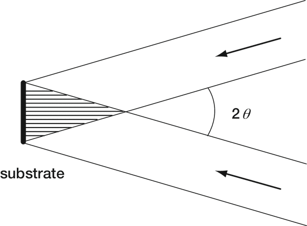
When two sets of coherent equally polarized monochromatic optical plane waves of equal intensity intersect each other, a standing wave pat-tern will be formed in the region of intersection if both sets of waves are of the same wavelength λ (see Figure 4-1). The combined intensity distribution forms a set of straight equally-spaced fringes (bright and darklines). Thus, a photographic plate would record a fringe pattern, since the regions of zero field intensity would leave the film unexposed while the regions of maximum intensity would leave the film maximally exposed. Regions between these extremes, for which the combined intensity is neither maximal nor zero, would leave the film partially exposed. The combined intensity varies sinusoidally with position as the interference pattern is scanned along a line. If the beams are not of equal intensity, the minimum intensity will no longer be zero, thereby decreasing the contrast between the fringes. As a consequence, all portions of the photographic plate will be exposed to some degree.
The centers of adjacent fringes (that is, adjacent lines of maximum intensity) are separated by a distance d, where
d = λ / 2sinθ (4-1)
and θ is the half the angle between the beams. A small angle between the beams will produce a widely spaced fringe pattern (large d), whereas a larger angle will produce a fine fringe pattern. The lower limit for d is λ/2, so for visible recording light, thousands of fringes per millimeter may be formed.
Formation of the Grooves
Master holographic diffraction gratings are recorded in photoresist, a material whose intermolecular bonds are either strengthened or weakened by exposure to light. Commercially available photoresists are more sensitive to some wavelengths than others; the recording laser line must be matched to the type of photoresist used. The proper combination of an intense laser line and a photoresist that is highly sensitive to this wavelength will reduce exposure time.
Photoresist gratings are chemically developed after exposure to reveal the fringe pattern. A photoresist may be positive or negative, though the latter is rarely used. During chemical development, the portions of a substrate covered in positive photoresist that have been exposed to light are dissolved, while for negative photoresist the unexposed portions are dissolved. Upon immersion in the chemical developer, a surface relief pattern is formed: for positive photoresist, valleys are formed where the bright fringes were, and ridges where the dark fringes were. At this stage a master holographic grating has been produced; its grooves are sinusoidal ridges. This grating may be coated and replicated like master ruled gratings.
Lindau has developed simple theoretical models for the groove profile generated by making master gratings holographically and shown that even the application of a thin metallic coating to the holographically-produced groove profile can alter that profile.
Single-beam Interference
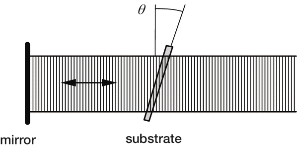
An interference pattern can be generated from a single collimated monochromatic coherent light beam if it is made to reflect back upon itself. A standing wave pattern will be formed, with intensity maxima forming planes parallel to the wavefronts. The intersection of this interference pattern with a photoresist-covered substrate will yield on its surface a pattern of grooves, whose spacing d depends on the angle θ between the substrate surface and the planes of maximum intensity (see Figure 4-2); the relation between d and θ is identical to Eq. (4-1), though it must be emphasized that the recording geometry behind the single-beam holographic grating (or Sheridon grating) is different from that of the double-beam geometry for which Eq. (4-1) was derived.
The groove depth h for a Sheridon grating is dictated by the separation between successive planes of maximum intensity (nodal planes); explicitly,
h = λ0 / 2n (4-2)
where λ0 is the wavelength of the recording light and n the refractive index of the photoresist. This severely limits the range of available blaze wavelengths, typically to those between 200 and 250 nm.
Double-beam Interference
The double-beam interference pattern shown in Figure 4-1 is a series of straight parallel fringe planes, whose intensity maxima (or minima) are equally spaced throughout the region of interference. Placing a substrate covered in photoresist in this region will form a groove pattern defined by the intersection of the surface of the substrate with the fringe planes. If the substrate is planar, the grooves will be straight, parallel and equally spaced, though their spacing will depend on the angle between the substrate surface and the fringe planes. If the substrate is concave, the grooves will be curved and unequally spaced, forming a series of circles of different radii and spacings. Regardless of the shape of the substrate, the intensity maxima are equally spaced planes, so the grating recorded will be a classical equivalent holographic grating (more often called simply a classical grating). This name recognizes that the groove pattern (on a planar surface) is identical to that of a planar classical ruled grating. Thus, all holographic gratings formed by the intersection of two sets of plane waves are called classical equivalents, even if their substrates are not planar (and therefore their groove patterns are not straight equally spaced parallel lines).
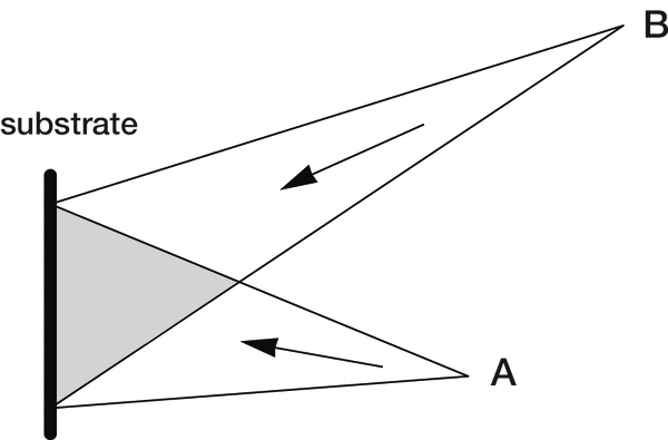
If two sets of spherical wavefronts are used instead, as in Figure 4-3, a first generation holographic grating is recorded. The surfaces of maxi-mum intensity are now confocal hyperboloids (if both sets of wavefronts are converging, or if both are diverging) or ellipsoids (if one set is con-verging and the other diverging). This interference pattern can be obtained by focusing the recording laser light through pinholes (to simulate point sources). Even on a planar substrate, the fringe pattern will be a collection of unequally spaced curves. Such a groove pattern will alter the curvature of the diffracted wavefronts, regardless of the sub-strate shape, thereby providing focusing. Modification of the curvature and spacing of the grooves can be used to reduce aberrations in the spectral images; as there are three degrees of freedom in such a recording geometry, three aberrations can be reduced.
The addition of auxiliary concave mirrors or lenses into the recording beams can render the recording wavefronts toroidal (that is, their curvature in two perpendicular directions will generally differ). The grating thus recorded is a second generation holographic grating.20 The additional degrees of freedom in the recording geometry (e.g., the location, orientation and radii of the auxiliary mirrors) provide for the reduction of additional aberrations above the three provided by first generation holographic gratings.
The use of aspheric recording wavefronts can be further accomplished by using aberration-reduced gratings in the recording system; the first set of gratings is designed and recorded to produce the appropriate recording wavefronts to make the second grating. Another technique is to illuminate the substrate with light from one real source, and reflect the light that passes through the substrate by a mirror behind it, so that it interferes with itself to create a stationary fringe pattern. Depending on the angles involved, the curvature of the mirror and the curvature of the front and back faces of the substrate, a number of additional degrees of freedom may be used to reduce high-order aberrations. [Even more degrees of freedom are available if a lens is placed in the recording system thus described.]
The Holographic Recording Process
Holographic gratings are recorded by placing a light-sensitive surface in an interferometer. The generation of a holographic grating of spectroscopic quality requires a stable optical bench and laser as well as high-quality optical components (mirrors, collimating optics, etc.). Ambient light must be eliminated so that fringe contrast is maximal. Thermal gradients and air currents, which change the local index of refraction in the beams of the interferometer, must be avoided. MKS records master holographic gratings in a clean room specially-designed to meet these requirements.
During the recording process, the components of the optical system must be of nearly diffraction-limited quality, and mirrors, pinholes and spatial filters must be adjusted as carefully as possible. Any object in the optical system receiving laser illumination may scatter this light toward the grating, which will contribute to stray light. Proper masking and baffling during recording are essential to the successful generation of a holographic grating, as is single-mode operation of the laser throughout the duration of the exposure.
The substrate on which the master holographic grating is to be produced must be coated with a highly uniform, virtually defect-free coating of photoresist. Compared with photographic film, photoresists are somewhat insensitive to light during exposure, due to the molecular nature of their interaction with light. As a result, typical exposures may take from minutes to hours, during which time an extremely stable fringe pattern (and, therefore, optical system) is required. After exposure, the substrate is immersed in a developing agent, which forms a surface relief fringe pattern; coating the substrate with metal then produces a master holographic diffraction grating.
For footnotes and additional insights into diffraction grating topics like this one, download our free MKS Diffraction Gratings Handbook (8th Edition)
Download a Handbook