Grating Monochromator Designs
A monochromator is a spectrometer that images a single wavelength or wavelength band at a time onto an exit slit; the spectrum is scanned by the relative motion of the entrance and/or exit optics (usually slits) with respect to the grating.
A plane grating is one whose surface is flat. Plane gratings are normally used in collimated incident light, which is dispersed by wavelength but is not focused. Plane grating mounts generally require auxiliary optics, such as lenses or mirrors, to collect and focus the energy. Some simplified plane grating mounts illuminate the grating with converging light, though the focal properties of the system will then depend on wavelength. For simplicity, only plane reflection grating mounts are discussed below, though each mount may have a transmission grating analogue.
The Czerny-Turner Monochromator
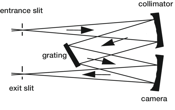
This design involves a classical plane grating illuminated by collimated light. The incident light is usually diverging from a source or slit, and collimated by a concave mirror (the collimator), and the diffracted light is focused by a second concave mirror (the camera); see Figure 6-1. Ideally, since the grating is planar and classical, and used in collimated incident light, no aberrations should be introduced into the diffracted wavefronts. In practice, since spherical mirrors are often used, aberrations are contributed by their use off-axis.
Like all monochromator mounts, the wavelengths are imaged individually. The spectrum is scanned by rotating the grating; this moves the grating normal relative to the incident and diffracted beams, which changes the wavelength diffracted toward the second mirror. Since the light incident on and diffracted by the grating is collimated, the spectrum remains at focus at the exit slit for each wave-length, since only the grating can introduce wavelength-dependent focusing properties.
Aberrations caused by the auxiliary mirrors include astigmatism and spherical aberration (each of which is contributed additively by the mirrors); as with all concave mirror geometries, astigmatism increases as the angle of reflection increases. Coma, though generally present, can be eliminated at one wavelength through proper choice of the angles of reflection at the mirrors; due to the anamorphic (wavelength-dependent) tangential magnification of the grating, the images of the other wavelengths experience higher-order coma (which becomes troublesome only in special systems).
The Ebert Monochromator
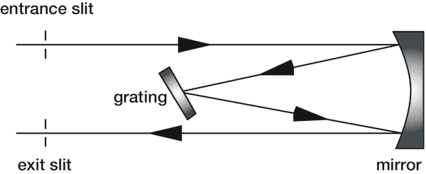
This design is a special case of a Czerny-Turner mount in which a single relatively large concave mirror serves as both the collimator and the camera (Figure 6-2). Its use is limited, since stray light and aber-rations are difficult to control – the latter effect being a consequence of the relatively few degrees of freedom in design (compared with a Czerny-Turner monochromator). This can be seen by recognizing that the Ebert monochromator is a special case of the Czerny-Turner monochromator in which both concave mirror radii are the same, and for which their centers of curvature coincide. However, an advantage that the Ebert mount provides is the avoidance of relative misalignment of the two mirrors.
Fastie improved upon the Ebert design by replacing the straight entrance and exit slits with curved slits, which yields higher spectral resolution.
The Monk-Gillieson Monochromator
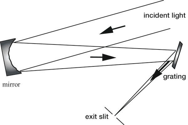
In this mount (see Figure 6-3), a plane grating is illuminated by converging light. Usually light diverging from an entrance slit (or fiber) is rendered converging by off-axis reflection from a concave mirror (which introduces aberrations, so the light incident on the grating is not com-posed of perfectly spherical converging wavefronts). The grating diffracts the light, which converges toward the exit slit; the spectrum is scanned by rotating the grating to bring different wavelengths into focus at or near the exit slit. Often the angles of reflection (from the primary mirror), in-cidence and diffraction are small (measured from the appropriate surface normals), which keeps aberrations (especially off-axis astigmatism) to a minimum.
Since the incident light is not collimated, the grating introduces wavelength-dependent aberrations into the diffracted wavefronts. Consequently, the spectrum cannot remain in focus at a fixed exit slit when the grating is rotated (unless this rotation is about an axis displaced from the central groove of the grating). For low-resolution applications, the Monk-Gillieson mount enjoys a certain amount of popularity, since it represents the simplest and least expensive spectrometric system imaginable.
The Littrow Monochromator
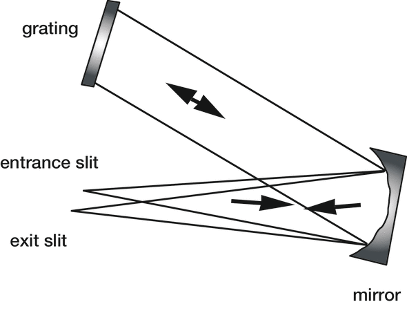
A grating used in the Littrow or autocollimating configuration diffracts light of wavelength λ back along the incident light direction (Figure 6-4). In a Littrow monochromator, the spectrum is scanned by rotating the grating; this reorients the grating normal, so the angles of incidence α and diffraction β change (even though α = β for all λ). The same auxiliary optics can be used as both collimator and camera, since the diffracted rays retrace the incident rays. Usually the entrance slit and exit slit (or image plane) will be offset slightly along the direction parallel to the grooves so that they do not coincide; this will generally introduce out-of-plane aberrations. True Littrow monochromators are quite popular in laser tuning applications.
Double and Triple Monochromator
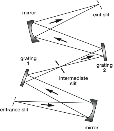
Two monochromator mounts used in series form a double monochromator. The exit slit of the first monochromator usually serves as the entrance slit for the second monochromator (see Figure 6-5), though some systems have been designed without an intermediate slit. Stray light in a double monochromator with an intermediate slit is much lower than in a single monochromator: it is approximately the product of ratios of stray light intensity to parent line intensity for each single monochromator.
A double monochromator may be designed to have either additive dispersion or subtractive dispersion.
- In the case of additive dispersion, the reciprocal linear dispersion of the entire system is the sum of the reciprocal linear dispersions of each monochromator: that is, the spectrum that is dispersed by the first monochromator is further dispersed in passing through the second monochromator.
- In the case of subtractive dispersion, the entire system is designed so that the spectral dispersion at the exit slit of the second monochromator is essentially zero. A subtractive-dispersion monochromator has the property that the light leaving its exit slit is spectrally uniform: the homogeneous combination of all wavelengths is transmitted through the intermediate slit, instead of a spectrum of continuous varying wavelength as seen in single monochromators and additive-dispersion double monochromators. Such instruments have found use in Raman spectroscopy systems (in which spectral features very close to the exciting laser wavelength can be observed), and in fluorescence and luminescence excitation.
A triple monochromator mount consists of three monochromators in series. These mounts are used when the demands to reduce instrumental stray light are extraordinarily severe.
The Constant-scan monochromator
The vast majority of monochromator mounts are of the constant deviation variety: the grating is rotated to bring different wavelengths into focus at the (stationary) exit slit. This mount has the practical advantage of requiring a single rotation stage and no other moving parts, but it has the disadvantage of being “on blaze” at only one wavelength – at other wavelengths, the incidence and diffraction angles do not satisfy the blaze condition
mλ = d(sinα + sinβ) = 2dsinθB (2-30)
where θB is the facet angle.
An alternative design that may be considered is the constant-scan monochromator, so called because in the grating equation
mλ = 2d cosK sinΦ (2-8)
it is the scan angle Φ rather than the half-deviation angle K that remains fixed. In this mount, the bisector of the entrance and exit arms must remain at a constant angle to the grating normal as the wavelengths are scanned; the angle 2K(λ) = α(λ) - β(λ) between the two arms must expand and contract to change wavelength.
Constant-scan plane grating monochromators have been designed50 but have not been widely adopted, due to the complexity of the required mechanisms for the precise movement of the slits. Hunter described a constant-scan monochromator for the vacuum ultraviolet in which the entrance and exit slits moved along the Rowland circle. The imaging properties of the constant-scan monochromator with fixed entrance and exit arms have not been fully explored, but since each wavelength remains on blaze, there may be applications where this design proves advantageous.
For footnotes and additional insights into diffraction grating topics like this one, download our free MKS Diffraction Gratings Handbook (8th Edition)
Download a Handbook