Focal Length and ƒ/#

For gratings (or grating systems) that image as well as diffract light, or disperse light that is not collimated, a focal length may be defined. If the beam diffracted from a grating of a given wavelength λ and order m converges to a focus, then the distance between this focus and the grating center is the focal length r'(λ). If the diffracted light is diverging, the focal length may still be defined, although by convention we take it to be negative (indicating that there is a virtual image behind the grating). Similarly, the incident light may diverge toward the grating (so we define the incidence or entrance slit distance r(λ) > 0) or it may converge toward a focus behind the grating (for which r(λ) < 0). Usually gratings are used in configurations for which r does not depend on wavelength (though the focal length r' usually depends on λ).

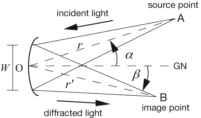
In Figure 2-7, a typical concave grating configuration is shown; the monochromatic incident light (of wavelength λ) diverges from a point source at A and is diffracted toward B. Points A and B are distances r and r', respectively, from the grating center O. In this figure, both r and r' are positive.

Figure 2-7. Geometry for focal distances and focal ratios (ƒ/numbers). GN is the grating normal (perpendicular to the grating at its center, O), W is the width of the grating (its dimension perpendicular to the groove direction, which is out of the page), and A and B are the source and image points, respectively.

Calling the width (or diameter) of the grating (in the dispersion plane) W allows the input and output ƒ/numbers (also called focal ratios) to be defined:

ƒ/#Input = r/W, ƒ/#Output = r' (λ)/W    (2-25)

Usually the input ƒ/number is matched to the ƒ/number of the light cone leaving the entrance optics (e.g., an entrance slit or fiber) to use as much of the grating surface for diffraction as possible. This increases the amount of diffracted energy while not overfilling the grating.

For oblique (non-normal) incidence or diffraction, Eqs. (2-25) are often modified by replacing W with the projected width of the grating:

ƒ/#Input = r/Wcosα, ƒ/#Output = r'(λ)/Wcosβ (2-26)

These equations account for the reduced width of the grating as seen by the entrance and exit slits; moving toward oblique angles (i.e., increasing |α| or |β|) decreases the projected width and therefore increases the ƒ/number.

The focal length is an important parameter in the design and specification of grating spectrometers, since it governs the overall size of the optical system (unless folding mirrors are used). The ratio between the input and output focal lengths determines the projected width of the entrance slit that must be matched to the exit slit width or detector element size. The ƒ/number is also important, as it is generally true that spectral aberrations decrease as ƒ/number increases. Unfortunately, increasing the input ƒ/number results in the grating subtending a smaller solid angle as seen from the entrance slit; this will reduce the amount of light energy the grating collects and consequently reduce the intensity of the diffracted beams. This trade-off prohibits the formulation of a simple rule for choosing the input and output ƒ/numbers, so sophisticated design procedures have been developed to minimize aberrations while maximizing collected energy.


Diffraction Gratings Handbook Cover

For footnotes and additional insights into diffraction grating topics like this one, download our free MKS Diffraction Gratings Handbook (8th Edition)

Download a Handbook