Technical Note:
Electro-Optic Modulator FAQs

General Modulator Questions

Q: What is the Pockel's effect?

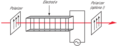
A: Both our phase and our amplitude modulators are based upon the Pockel's effect: the electro-optic effect where the refractive index along one or more axes is proportional to an externally applied electric field. Therefore, by applying a voltage across the electrodes of an electro-optic crystal, you can change the phase of light as it passes through the crystal. By placing the crystal between crossed polarizers, this phase modulation can be converted into amplitude modulation.

Q: Can phase modulators be used in interferometric applications?

A: No, the electro-optic crystals that we use in our phase modulators contain refractive index inhomogeneities. This spatially non-uniform refractive index imparts a significant wavefront distortion to any beam that passes through the modulator. When the beams are recombined, the wavefront distortion will cause the on:off contrast ratio to be very low, perhaps 3:1 or 5:1.

Q: Can these bulk modulators be packaged with optical fibers?

A: All the modulators that we manufacture are bulk modulators, and, as such, only work with free-space beams. We do not have a fiber-coupled option for these modulators.

Q: What is the half-wave voltage or Vp?

A: This is the voltage (specified either at DC or at the maximum operating frequency) required to achieve a phase shift equal to p (3.14) radians. It is proportionately smaller at shorter wavelengths, and is much smaller for resonant devices due to the voltage enhancement provided by the resonant circuit or cavity on resonance. For amplitude modulators, Vp is the voltage necessary to change from maximum transmission to maximum extinction. With our amplitude modulators, this requires external polarizers such as the Model 5526 Glan-Thompson polarizers.

Q: What's the modulation depth at a given wavelength?

A: The modulation depth is the resulting phase change when 1 V (peak) is applied to the modulator, and is inversely proportional to the Vp. We specify the modulation depth at 1.06 µm. Since it is proportionately larger at shorter wavelengths, the modulation depth at 532 nm is twice that at 1.06 µm. The modulation depth is much larger for resonant phase modulation because the resonant circuit provides voltage enhancement when operating on resonance.

Q: What's the difference between a resonant modulator and a broadband modulator?

A: A resonant modulator operates at a specified frequency while a broadband modulator can operate over a wide frequency range. In a resonant modulator, the crystal is placed in a resonant circuit or cavity tuned to a particular frequency. Because the crystal voltage can be more than ten times the input drive voltage when operating near that particular frequency, resonant devices require significantly lower input voltage, and are easier to operate than broadband modulators. Keep in mind that the resonant frequency of the Model 4001 and 4003 modulators isn't tunable. Typically the resonance has a bandwidth of 2-4% of the resonant frequency, allowing the device to be operated over this narrow frequency range. In contrast, the high-frequency resonant cavity modulators (Models 442X, 443X and 485X) are equipped with a tuning screw that allows the resonant frequency to be adjusted over a 100-MHz range.

To compare the advantages of resonant enhancement, we can compare the half-wave voltage, Vp, the voltage required to produce a p phase shift. The Vp of a broadband phase modulator at 1.06 µm is 210 V, corresponding to a modulation depth of 0.015 rad/V. These values scale with wavelength, so at 532 nm, Vp is 105 V and the modulation depth is 0.03 rad/V. In contrast, the Model 4001 and 4003 resonant phase modulators have much higher modulation depths: Vp at 1.06 µm is typically 10-31 V, corresponding to a modulation depth of 0.1-0.3 rad/V (0.3 rad/V in the low-frequency range of 0.01-20 MHz dropping to 0.1 rad/V at high frequencies of 120-190 MHz).

Q: What is the Q, or quality factor, of the modulators?

A: The quality factor Q is a universal measure of how well a resonator can build up large field intensities with moderate input powers. For the Model 4001 and 4003 low-frequency resonant modulators, the typical Q is between 20-40. For the Model 44XX and 48XX high-frequency resonant modulators, the typical Q will be between 100-200.

Q: How do I order a resonant modulator?

A: When ordering a resonant modulator, you will need to specify a frequency. Keep in mind that our resonant phase modulators are not available at frequencies from 190 to 500 MHz. This gap exists because the 400X modulators use discrete inductors that do not perform well above 190 MHz, and the 442X modulators employ a resonant cavity that is not suitable for use below about 500 MHz.

In the > 6 GHz frequency range, we offer the Model 485X, which operates at 6.8 or 9.2 GHz. With some modification, this device can be designed to operate at other discrete frequencies in the 6-11-GHz range. If you are interested in a custom frequency, please contact us for details.

Note: that if you do not need to operate your modulator at a specific frequency, then it might be possible for us to increase the modulation depth slightly by having it operate at a slightly different frequency. So if you do not need to operate at a specific frequency, we can try to build a modulator so it performs at whatever frequency is best, and then we can notify you of this resonant frequency after the modulator has been characterized.

Q: How does a piezo resonance affect a modulator's performance?

A: Because all electro-optic crystals are also piezoelectric, sometimes phase modulation can be accompanied by unwanted amplitude modulation and beam deflection. This effect is most dramatic when the crystal is driven at a frequency that coincides with an acoustic resonance. By avoiding these piezoelectric resonances, the most problematic of which are in the 1-100-MHz range, your modulator performance will be unaffected by piezo effects.

We test the Model 4001 and 4003 resonant phase modulators for the presence of piezo resonances. If a piezo resonance is found at the resonant frequency you requested when ordering a modulator, the modulator frequency will need to be shifted by ±2 MHz. We will contact you if such a change in resonant frequency becomes necessary.

Q: What is the RF electrical bandwidth?

A: This is the operating range of the device, otherwise known as the 3-dB frequency, and refers to the width of the electronic resonance for our resonant electro-optic modulators. It is the frequency where the electrical power transferred to the modulator has decreased by a factor of two. This is equivalent to where the modulator optical performance has changed by 1.414, since modulation is proportional to electrical field strength and not electromagnetic power. This bandwidth is typically 0.5% of the resonant frequency (this corresponds to ±0.25% of the resonant frequency). For example, the Model 4431 operating at 3 GHz has a typical electronic bandwidth of about 15 MHz (or, 0.5% of 3 GHz). These modulators are also equipped with a tuning element that allows the resonant frequency to be tuned manually over a range of at least 100 MHz. So, the Model 4431 operating at 3 GHz can generally be manually tuned from about 2.95 to 3.05 GHz.

Q: What is VSWR?

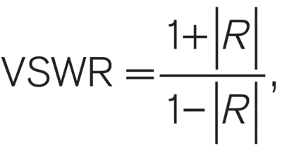
A: The voltage standing-wave ratio (VSWR) is defined as the ratio between the maximum and minimum voltage along a standing wave that results from electrical reflections due to an impedance mismatch. A VSWR value of 1 indicates a perfectly matched system. Since the VSWR is related to the reflection coefficient R by:

it tells you how much power will be reflected back to your driver. Excessive reflected RF power can damage your source. A VSWR of 1.5 corresonds to 4% of the incident RF power reflected back to the driver.

Q: Do the crystals have an antireflection coating?

A: Yes, we AR coat the crystals with one of two standard broadband antireflection coatings with a reflectivity <1%: 500-900 nm, and 1.0-1.6 µm. We can also custom V-coat the crystals for a reflectivity of <0.25%. There is an additional charge for this custom coating.

Q: How much insertion loss can I expect?

A: Losses come from poor AR-coating and absorption. Our AR coating has 1% maximum reflectivity per surface, and our crystals typically have losses of 0.3%/cm at 1 µm. So in a typical modulator which is 4 cm long, you can expect a total insertion loss of about 3.2%. If you need a lower reflectivity, we offer custom coatings. Call us for more details.

Q: What's the easiest way to get the beam through the modulators? What polarization and beam size?

A: To align the modulator, we suggest using the Model 9071 four-axis tilt aligner. In order to minimize clipping through the modulator, a good rule of thumb is that the beam diameter should be less than one-third the aperture size. For example, a modulator with a 2-mm aperture can accommodate a 0.7-mm-diameter beam. Larger beams can be focused into the modulator and then collimated afterwards using a pair of lenses. If you do this, make sure the intensity inside the modulator doesn't exceed the damage threshold. For the phase modulators, the laser beam should be well collimated and its polarization should be oriented vertically to within 1°. For our amplitude modulators, the beam can be either vertically or horizontally polarized. For an unpolarized laser, the polarizer should have an extinction ratio greater than 100:1. We recommend our Model 552X Glan-Thompson polarizers or our low-cost Model 5511 sheet polarizers.

Q: What is the optical damage mechanism for these modulators?

A: For lithium niobate crystals, optical damage is caused by the photorefractive effect. This effect is related to the average optical power, not the peak power, and is wavelength and intensity dependent. For instance, the photorefractive damage process can occur gradually over days or hours, or, in the case of high optical powers and short wavelengths, in seconds. Photorefractive damage is a result of photoexcited charge carriers migrating from illuminated regions to dark regions. This in conjunction with the electro-optic effect causes local variations in the refractive index, which then reduces the effectiveness of the modulators and causes beam distortions.

For the magnesium oxide doped (MgO) lithium niobate, the damage thresholds are 4 W/mm2 at 670 nm in a 1-mm diameter beam. The MgO doping increases the resistance to photorefractive damage, enabling this material to be used in the visible wavelength range. With a 0.5-mm diameter beam, the maximum threshold is considerably lower at about 0.5 W. At 1.54 µm the damage threshold is about 5 W average power in a 0.5-mm diameter beam. In comparison, non-doped lithium niobate has a damage threshold of 1 W/mm2 at 1.3 µm in a 1-mm beam.

If the crystal exhibits photorefractive damage, the damage can be removed by heating (annealing) the crystal slowly to about 50-70 °C, thereby mobilizing the charge carriers. Also, exposing the crystal to a UV light source can also help remove photorefractive damage. Please contact us before performing any of these measures since there may be internal parts that cannot handle the elevated temperatures.

Note: Typically, the damage issue is most problematic for wavelengths shorter than 600 nm, where the photorefractive damage process becomes more efficient: keep in mind that the maximum optical power drops off sharply as the wavelength gets shorter.

Q: Where can I find a driver for the broadband modulators?

A: The type of driver you need depends on which modulator you have and how it's being used. The Model 4002, 4004, and 4104 broadband devices have no internal impedance matching, so the modulator's input impedance is determined only by the crystal capacitance (10-20 pF). For these devices, it is important to use a source that can drive a capacitive load. Achieving a p phase shift requires a drive voltage from 100 to 400 V, depending on wavelength. For these modulators and for frequencies from DC to 0.6 MHz, you can use a function generator followed by the New Focus Model 3211 high-voltage amplifier. The Model 3211 can supply ±200 V into a capacitive load (C<100 pF) at frequencies up to 600 kHz. Keep in mind, however, that some broadband applications require only small-signal modulation, in which case a broadband modulator driven by a low-voltage driver might be adequate. In this case, since the modulator appears as a capacitor to the driving circuit, the RF bandwidth is determined by the combined RC-time constant of the modulator and driving circuit. For the typical case of a 50-W oscillator and a 20-pF modulator, the maximum bandwidth is about 100 MHz.

For higher frequencies customers need to obtain their own electronic driver. One thing to keep in mind is that although these broadband modulators have the capability of being driven at frequencies to 100 and 200 MHz, in practice it can be very difficult to find a high-voltage driver that is capable of supplying 200 volts at frequencies above about 1 MHz into a 10-20 pF capacitive load. One approach is to use a pulsed driver operating at a low duty cycle. Alternately, for single-frequency applications above 1 MHz where a phase shift of about 1 radian is required, we recommend using our Model 4001 or 4003 resonant phase modulators.

The companies listed below supply high-voltage amplifiers and/or pulse generators.

Avtech Electrosystems Ltd. (Pulse generators, pulse and CW amplifiers)
Phone: 800-265-6681 (or, 613-226-5772)
FAX: 800-561-1970 613-226-2802
E-mail: info@avtechpulse.com

Berkeley Nucleonics Corp. (Pulse generator - Model 6040 with the 202H module)
Phone: 415-453-9955 (or, 800-234-7858)
FAX: 415-453-9956
E-mail: berkeley@berkeleynucleonics.com
www.berkeleynucleonics.com

Directed Energy, Inc. (Pulse generators)
Phone: 970-493-1901 FAX: 970-493-1903
E-mail: deiinfo@dirnrg.com
www.directedenergy.com

Q: Where can I find a driver for the resonant modulators?

A: New Focus does not sell RF sources for driving resonant phase and amplitude modulators (this includes Models 443X and 485X). These crystals are placed in a resonant circuit or cavity tuned to a particular frequency. By matching the input impedance to 50 Ohm when operating on resonance the power transfer to the crystal is maximized, and these devices require significantly lower drive voltages than the broadband versions. Some of the low-frequency (<200 MHz) resonant modulators (Models 4103, 4001, and 4003) can be driven directly by a low power RF oscillator (crystal oscillator, or synthesizer), or a function generator whose source impedance is 50 Ohm. The other high frequency (>0.5 GHz) modulators typically require a RF source that consists of a low power oscillator or function generator followed by a RF amplifier. The source and amplifier should be matched to 50 Ohm and capable of generating 1 to 4 watts of RF power. Depending on the frequency range and RF power requirements for their modulation application, you can contact the companies listed below.

Hewlett-Packard (Function generators and low-power RF amplifiers for 1 MHz to 13 GHz.)
Phone: 800-452-4844 (in USA)
www.hp.com

Wavetek (Function generators up to 50 MHz.)
Phone: 619-279-2200
FAX: 619-450-0325
www.wavetek.com

Mini-Circuits (RF amplifiers and oscillators from DC to 4.2 GHz.)
Phone: 800-654-7949 (or, 718-934-4500)
FAX: 718-332-4661
www.minicircuits.com

Miteq (RF amplifiers and oscillators from .1 to 13 GHz.)
Phone: 516-436-7400
FAX: 516-436-7430
www.miteq.com

Vectron (Oscillators from 1 MHz to 2.6 GHz.)
Phone: 203-853-4433
FAX: 203-849-1423
www.vectron.com

JCA Technology, Inc. (Custom RF amplifiers for driving the 485X modulators.)
Phone: 805-445-9888
FAX: 805-987-6990
www.jcatech.com

Quinstar Technology (Custom RF amplifier products that can drive the 485X modulators.)
Phone: 310-320-1111
FAX: 310-320-9968
E-mail: sales@quinstar.com

Microwave Amplifiers Ltd. (Bristol, England) (RF amplifiers for the 442X, 443X, and 485X modulators.)
Phone: +44 1275 853196
FAX: +44 1275 858502
E-mail: sales@maltd.com
www.maltd.com

Z-Communications, Inc. (RF oscillators up to 7 GHz)
Phone: 619-621-2700
FAX: 619-621-2722
www.zcomm.com

Amplifier Research (RF amplifiers and TWT amplifiers from DC to 40 GHz)
Phone: 215-723-8181
FAX: 215-723-5688
www.ar-amps.com

Phase Modulator Questions

Q: What's the difference between frequency modulation and phase modulation?

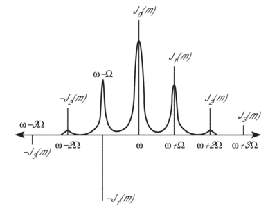
A: Because of the mathematical relationship between frequency and phase, phase modulation isn't possible without frequency modulation and vice versa. Phase modulators are used to vary the phase of an optical beam. Sinusoidal phase modulation at a frequency W generates frequency sidebands at multiples of W about the central cw optical frequency, W.

2002 Bessel Function
Bessel Function: This spectrum of a phase-modulated electric field is given by Bessel functions. The amplitude in the kth sideband at w+kW is proportional to Jk(m), where Jk is the kth order Bessel function and m is the peak phase modulation. The optical intensity of each sideband is proportional to the square of the electric field amplitude.
97 NEW FOCUS 2
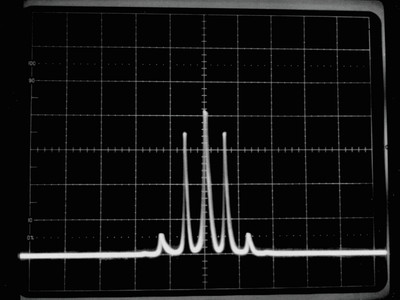
Transmitted Intensity Spectrum: This spectrum was taken using a scanning Perot-Fabry optical spectrum analyzer. The 1.06-µm laser was phase modulated with a Model 4003 resonant phase modulator. The driving frequency was 7.94 MHz and the peak voltage was 3 V.

A: Given a sinusoidal phase modulation at frequency W and with a peak phase change m, the phase variation is f(t)=msin(Wt). The electric field of the optical beam after passing through the modulator can be written:

A: The amplitude of the kth sideband is proportional to Jk(m), where Jk is the Bessel function of order k. The fraction of optical power transferred into each of the first-order sidebands is [J1(m)]2, and the fraction of optical power that remains in the carrier is [J0(m)]2. For example, imposing a phase modulation with peak phase shift of 1 radian will transfer 19% of the initial carrier power to each of the first-order sidebands and leave 59% of the power in the carrier. The maximum power that can be transferred to the first-order sidebands is about 34%, which requires a peak phase shift of 1.8 radians.

Q: How much residual amplitude modulation (RAM) is there?

A: A perfect phase modulator will have no RAM. However, residual étalons in the modulator crystal will lead to amplitude modulation. With careful adjustment of the optical beam's alignment and polarization, you can expect a residual amplitude modulation of -60 dB for a 1-radian peak phase shift.

Q: Can I use your phase modulator as an amplitude modulator?


2002 bulk phase mod dwg
New Focus bulk phase modulator

A: Our phase modulators will not make good amplitude modulators. First, the phase modulators use just one electro-optic crystal. Since these crystals exhibit thermal birefringence, a phase modulator will have significant problems with thermal drift if it is used as an amplitude modulator. New Focus addresses this problem in our amplitude modulators by using two orthogonal crystals to cancel out the static birefringence. During phase modulation, thermal problems are less significant, because the input beam is polarized along one of the crystal axes. The thermal drift simply produces a DC phase shift. In most phase modulators, this is equivalent to adding a few microns to the optical path length.

Second, most of our phase modulators are made with MgO-doped lithium niobate crystals. This material works well for phase modulation, and the MgO doping helps to increase the material's resistance to photorefractive damage. However, one drawback to this material is that it exhibits increased wavefront distortion (as compared with lithium tantalate or undoped lithium niobate). For most phase modulation applications, wavefront distortion of the optical beam does not present any problems, but when used as an amplitude modulator, the wavefront distortion causes poor on:off contrast ratios.

Q: With the Model 485X and 443X modulators, can I tune the modulator's resonant frequency?

A: Although these modulators are shipped with a specific resonant frequency they can be tuned over a range greater than 100 MHz. The tuning element is simply a brass slug that screws into the resonant cavity and causes the resonant frequency to shift. The modulator's resonant frequency will drift over long time periods and as the modulator's temperature changes. So, we recommend optimizing the frequency match between your RF driver and the modulator each time you use the modulator. This can be done by tuning the frequency of your RF oscillator and looking for the maximum modulation effect from the modulator. Or, you can hold the RF oscillator frequency constant and turn the tuning element until the modulation is maximized.

Q: What precautions should I take when driving a modulator with more than 1 watt of RF power?

A: For the Models 442X, 443X and 485X, the modulator's temperature will increase noticeably when driven with greater than 1 watt of RF power. To prevent damage to your RF driver you should optimize the frequency match between the modulator and driver continuously until the modulator reaches a constant operating temperature and the resonant frequency has stabilized. In addition, to improve the modulator's temperature stability you can cool the device using a small fan. Or, the black plastic mounting base can be removed allowing the modulator to be mounted directly onto a metal surface for heat conduction.

Q: Can I use a phase modulator for laser stabilization?

A: Pound-Drever Hall Laser Frequency Stabilization System Yes, a Model 4001 or 4003 resonant phase modulator with a Model 3211 high-voltage amplifier is the ideal component for use in Pound-Drever-Hall laser frequency stabilization system. This optical FM frequency discriminator technique* is used to lock the optical frequency of a laser to a stable Fabry-Perot reference cavity. The system consists of a single-frequency laser beam that is sinusoidally phase modulated and coupled into an axial mode of the Fabry-Perot resonator cavity. The stabilization signal is fed back to a Model 3211 high-voltage amplifier that drives a piezoelectric transducer. The frequency-stabilized light transmitted by the cavity is clean spatially as well as spectrally. *Drever, R. W. P., et al. "Laser Phase and Frequency Stabilization Using an Optical Resonator," Appl. Phys. B31, 97Ð105 (1983).

Amplitude Modulator Questions

Q: How do the amplitude modulators work?

2002 bulk amp mod dwg
New Focus bulk amplitude modulators

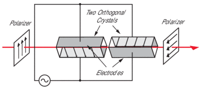
A: Amplitude modulators basically consist of an electro-optic modulator followed by a polarizer. If the input polarization is oriented at 45° to the crystal axes, the applied voltage will produce a variable phase delay between the ordinary and extraordinary field components, simulating a voltage-tunable waveplate. Thus, the modulation of the intensity is a sin2 function. New Focus simplifies your optical setup by mounting the crystal at 45°. Thus, the input polarization can be either vertical or horizontal.

In order to suppress birefringence variations due to temperature changes, we use two matched crystals arranged in series with their applied electric fields oriented at 90° relative to each other. Our amplitude modulators exhibit less than 1 mrad/°C of temperature-dependent polarization rotation. We cancel thermal birefringence while doubling the electro-optically induced polarization rotations by reversing the crystal axes such that both polarization components travel equal optical paths in the ordinary and extraordinary orientations.

Note: that the 4103 and 4104 are not supplied with polarizers, and so, at the output of the modulator you will need a polarizer such as the Model 5526 Glan-Thompson polarizer.

Q: What is the extinction ratio?

A: The extinction ratio of an amplitude modulator is the ratio between the optical power at maximum and minimum transmission. A high extinction ratio indicates a good modulator. For our Model 410X modulators, the extinction ratio is limited by refractive-index distortions in the electro-optic crystals that impart wavefront distortion to the optical beam. For these devices, the on:off extinction ratio is typically 50:1 for a 0.5-mm-diameter beam. Higher values can be achieved by focusing your beam.

Q: How do I optimize the contrast ratio with our amplitude modulators?

A: The electro-optic crystals used in the modulator have some residual birefringence that is spatially dependent. So, when the modulator is first inserted between a pair of crossed polarizers, it is normal to observe some light passing through the polarizers.

In order to optimize the performance of the modulator, you will need to adjust the position of the modulator with respect to the He-Ne laser beam. The Model 9071 4-axis tilt aligner can be useful for mounting the modulator and performing fine-adjustment of the modulator's position. Once the modulator is inserted between crossed polarizers, we recommend that you make small adjustments to the orientation of the modulator with respect to the optical beam until the amount of light that passes through the second polarizer is minimized.

You can measure the contrast ratio

([Power transmitted in the on state]/[Power transmitted in the off state])

by rotating the second polarizer and measuring the on:off ratio. Or, you can measure the contrast ratio by applying voltage to the modulator to turn it from off to on. With a He-Ne laser positioned about one foot from the modulator (approximately 0.5-mm beam diameter), we typically measure a contrast ratio of 50:1.

Q: How do I get linear amplitude modulation?

99-mod transfer function rev
Transfer function of our amplitude modulators

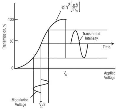
A: The transfer function of an amplitude modulator between crossed polarizers is a sin2 function. You can achieve linear amplitude modulation with small modulation voltages by biasing the modulator at the 50% transmission point, either with a quarter-wave plate or by applying a DC voltage to the modulator.

Q: Can I use a Model 410X amplitude modulator as an optical switch or for optical chopping?

A: Yes, the Models 4103 and 4104 amplitude modulators can be used as optical switches or for optical chopping. For a 1-mm diameter beam these devices have typical on:off extinction ratios of 50:1 or greater. The Model 4104 is a broadband modulator that can be operated over a wide frequency range. This device requires about 450 volts to turn 1.6 µm light on and off. Our Model 3211 high-voltage amplifier can be used to drive the Model 4104. However, the 3211 only operates from DC to 600 kHz, and the maximum output voltage is +200 to -200 volts.

For higher frequencies you can use the Model 4103, which is a resonant amplitude modulator. The 4103 requires a much lower drive voltage, but since it uses a resonant circuit, the 4103 can only be operated at one customer-specified frequency from 10 kHz to 200 MHz. By chopping at these higher frequencies far away from the 1/f noise, you can achieve shot-noise-limited detection.

Q: If I use an amplitude modulator as an electronically variable waveplate, how much wavefront distortion is there?

A: If you are using the amplitude modulator as a quarter waveplate, we calculate a ±2% error in the quarter waveplate over a 1-mm diameter beam. This means that over a certain portion of the input beam, you will have a quarter waveplate. Other portions of the beam can be off by >2%. Because the index distortion varies across the crystal, you cannot adjust the electrical signal to compensate for the index distortion across the crystal.

Q: Can I use the amplitude modulator as a rotating fixed waveplate?

A: No, the Models 4103 and 4104 amplitude modulators can be used as variable waveplates only. They will not work as a substitute for a rotating fixed wave plate. The Model 410X modulators function as a waveplate whose retardance is varied by changing the voltage that is applied to the electro-optic crystals. So, you can simulate a waveplate with a fixed orientation and an electronically variable retardance. A rotating fixed waveplate would require a fixed retardance with a variable orientation, which is not possible with the 410X.

High Voltage Amplifier Questions

Q: What type of loads can the amplifier drive?

A: The Model 3211 high-voltage amplifier is designed to drive capacitive loads up to 100 nanofarads with voltage swings of ±200 Volts. This includes electro-optic modulators and piezoelectric transducers.

Q: What is the maximum operating bandwidth of the high-voltage amplifier?

A: The load capacitance and output voltage together determine the maximum operating bandwidth of the Model 3211 high-voltage amplifier. For capacitive loads of less than 100 pF, the Model 3211 can output the full ±200 volts up to a maximum frequency of 600 kHz. For capacitive loads greater than 100 pF, the maximum bandwidth decreases. For 100-nF, the maximum bandwidth is about 800 Hz. For a 1000-pF load, the maximum operating bandwidth is approximately 80 kHz.

Q: What is the absolute maximum bandwidth of the high-voltage amplifier?

A: The Model 3211 high-voltage amplifier has an absolute maximum bandwidth of 600 kHz and a maximum slew rate of 700 V/µs. The maximum bandwidth and slew rate are determined by the speed of the op-amp that is used in this instrument.

Optical Chopper Questions

Q: What differentiates the Model 3501 optical chopper from others on the market today?

A: What makes the Model 3501 optical chopper special is its low phase noise very near the chopping frequency. Most choppers specify their phase noise in the time domain as a root-mean-square (rms) deviation in degrees or as a peak-to-peak value in microseconds. In the case of the Model 3501 chopper, the internal frequency synthesizer gives you <10-ppm/°C frequency stability and ±100-ppm frequency drift with 0.4° phase jitter at 1 kHz. However, for applications using lock-in amplifiers, the frequency-domain characteristics are more important and this time-domain specification is misleading. A more revealing way to characterize chopper performance in the frequency domain is by measuring the phase noise with a spectrum analyzer. While a time-domain experiment is sensitive to the integrated effects of residual phase modulation, a frequency-domain experiment like lock-in detection is only sensitive to phase noise within a detection bandwidth (typically a few hertz) of the chopping frequency. So phase noise far away from the chopping frequency that contributes to the RMS-phase deviation does not contribute to the noise floor in a lock-in experiment. When compared to other choppers with the same time-domain jitter specification, the Model 3501 has much lower phase noise close to the chopping frequency. In other words, the Model 3501, with its frequency-locking circuitry, is much more stable than a typical voltage-controlled chopper. What this means to you is increased sensitivity and a lower noise floor when using the Model 3501 with a lock-in amplifier.

99a-3501 Chopper freq graph
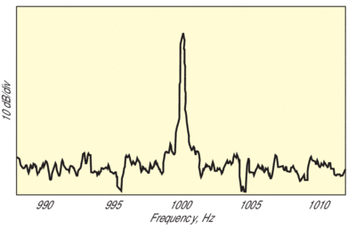
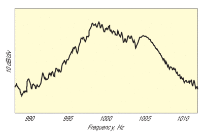
New Focus Chopper: At frequencies close to the chopping frequency, the Model 3501 optical chopper has much lower phase noise than a typical voltage controlled chopper. This is because of the stability provided by the phase-locked crystal-controlled design of the Model 3501.
99a-3501 chpr graph
Typical voltage controlled chopper

Q: How does the Model 3501 optical chopper minimize jitter and drift?

A: For stable chopping with minimum jitter and drift, the Model 3501 optical chopper uses precision photo-etched wheels mounted on a high-quality DC motor. In addition, the chopper controller has its own internal crystal-controlled frequency synthesizer and phase-locked loop for precisely locking the chopping frequency. A photo-interrupter on the chopper head monitors the chopping frequency, and the chopper controller actively stabilizes the motor speed to ensure stable chopping with a minimum of frequency drift. In internal-reference mode, the chopper controller uses its internal frequency synthesizer as the reference. When the Model 3501 is operated in external-reference mode, the chopping rate is locked to the user-provided reference from another chopper or signal source. The chopper may also be run asynchronously with the rear-panel analog-control-voltage input. In all cases, the frequency-synthesizer output is available on the front panel for use in your measurement setup. The reference signal can be divided and multiplied by the sub-harmonic and harmonic generators before being processed by the phase shifter. The microprocessor-controlled system provides flexibility and performance never before available in an optical chopper.

Q: What's the jitter of the chopper?

A: The Model 3501 chopper exhibits some jitter at all chopping frequencies. The jitter is typically largest at the lowest chopping frequency because it is difficult to maintain a constant rotational speed when the motor is rotating very slowly (2 Hz). We don't have any detailed specifications for rms phase jitter versus chopping frequency. Here are some approximate numbers for jitter at minimum and maximum chopping frequencies - for the 60 slot wheel operating at 120 Hz, the jitter is about 60 µs (peak-to-peak), and for the 60 slot wheel operating at 6.4 kHz, the jitter is about 2 µs (peak-to-peak).

Q: Is the Model 3501 optical chopper compatible with lock-ins from other companies?

A: Yes, the Model 3501 is completely compatible with lock-in amplifiers sold by other companies.

Q: Is it possible to lock together two choppers?

A: It is certainly possible to operate two choppers together and have one chopper supply the locking signal for the other. In this case, both choppers will be phase-locked. The first chopper locks to its internal oscillator and it supplies a reference signal to the second chopper. The second chopper is then locked to this external input, rather than locking to its own internal oscillator.

Q: Does the chopping refer to the on/off chopping frequency or the rotational speed of the chopper?

A: The chopper frequency refers to the on/off chopping frequency that can be generated by the wheel chopping a laser beam; it does not refer to the rotational speed of the chopper motor. For instance, the rotational speed of the chopper motor goes from a minimum of 2 rotations per second up to a maximum of 106.5 rotations per second. Therefore, the 2-slot wheel has a chopping frequency range of from 4 Hz to 213 Hz.

Q: Can the chopper be used at higher frequencies than listed in the catalog?

A: No, the Model 3501 chopper has a chopping frequency range from 4 Hz to 6.4 kHz. This device does not have the capability for synthesized chopping at higher frequencies.

Q: When I operate the chopper, the wheel looks like it's wobbling. Is that a problem?

A: Typically, wheel "wobble" should not affect performance of the chopper unit. Because of the design of the photodetector/LED unit on the bottom of the chopper, the wheel should never wobble enough to distort the lock signal. If the wheel wobbles and hits either the detector or LED then we need to replace the wheel. If the wheel only wobbles slightly, then the unit should perform within specification. If the wobble creates a problem, then the wobble will affect the locking signal and the "unlocked" light on the controller will never turn off or may flash (excessive jitter). This would require us to replace the wheel.

Q: I want to avoid the additional warm-up time of one hour required for operation at a very specific frequency (1/10000 of the set frequency). How can I do this?

A: There are a few methods that can set the unit in "standby" mode, that is with the electronics warmed up, but the chopper head off or running at a minimal speed.

Leave the driver on with the selected wheel spinning at 10% of maximum frequency. (The unit will operate better if the driver is not left on minimum drive frequency). Leave the driver unit on with the chopper head disconnected. Turn the unit off when reconnecting the chopper head. Then turn the unit back on. Set the driver up to run on an external sync. The unit will wait until a signal comes in before it begins to turn. This will put the unit in standby mode without the chopper head spinning. This is a better way of setting the unit in a standby mode then connecting and disconnecting the chopper head cable.