Concave Grating Spectrometer Designs
As with plane grating mounts, concave grating mounts can be used in either monochromators or spectrographs designs.
The Rowland circle spectrograph
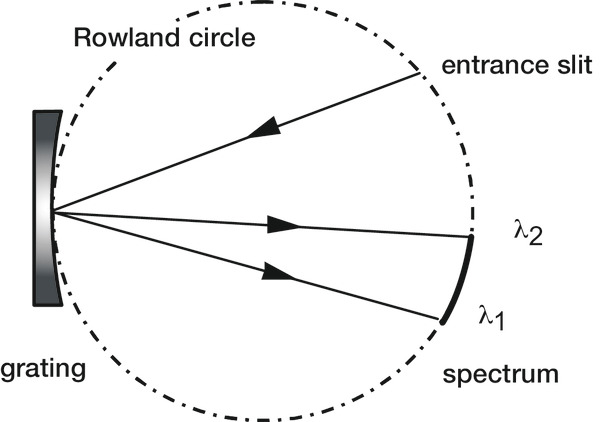
The first concave gratings of spectroscopic quality were ruled by Rowland, who also designing their first mounting. Placing the ideal source point on the Rowland circle (see Eqs. (7-12) and Figure 7-5) forms spectra on that circle free from defocus and primary coma at all wavelengths (i.e., F20 = F30 = 0 for all λ); while spherical aberration is residual and small, astigmatism is usually severe. Originally a Rowland circle spectrograph employed a photographic plate bent along a circular arc on the Rowland circle to record the spectrum in its entirety.
Today it is more common for a series of exit slits to be cut into a circular mask to allow the recording of several discrete wavelengths photoelectrically; this system is called the Paschen-Runge mount. Other configurations based on the imaging properties of the Rowland circle are the Eagle mount and the Abney mount, both of which are described by Hutley78 and by Meltzer.
Unless the exit slits (or photographic plates) are considerably taller than the entrance slit, the astigmatism of Rowland circle mounts usually prevents more than a small fraction of the diffracted light from being recorded, which greatly decreases the efficiency of the instrument. Increasing the exit slit heights helps collect more light, but since the images are curved, the exit slits would have to be curved as well to maintain optimal resolution. To complicate matters further, this curvature depends on the diffracted wavelength, so each exit slit would require a unique curvature. Few instruments have gone to such trouble, so most Rowland circle grating mounts collect only a small portion of the light incident on the grating. For this reason, these mounts are adequate for strong sources (such as the observation of the solar spectrum) but not for less intense sources (such as stellar spectra).
The imaging properties of instruments based on the Rowland circle spectrograph, such as direct readers and atomic absorption instruments, can be improved by the use of nonclassical gratings. By replacing the usual concave classical gratings with concave aberration-reduced gratings, astigmatism can be improved substantially. Rowland circle mounts modified in this manner direct more diffracted light through the exit slits, though often at the expense of degrading resolution to some degree.
The Wadsworth spectrograph
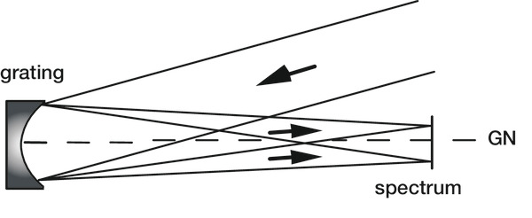
When a classical concave grating is illuminated with collimated light (rather than from a point source on the Rowland circle), spectral astigmatism on and near the grating normal is greatly reduced. Such a grating system is called the Wadsworth mount (see Figure 7-6). The wavelength-dependent aberrations of the grating are compounded by the aberration of the collimating optics, though use of a paraboloidal mirror illuminated on-axis will reduce off-axis aberrations and spherical aberrations. The Wadsworth mount suggests itself in situations in which the light incident on the grating is naturally collimated (from, for example, astronomical sources). In other cases, an off-axis parabolic mirror would serve well as the collimating element.
The Wadsworth spectrograph
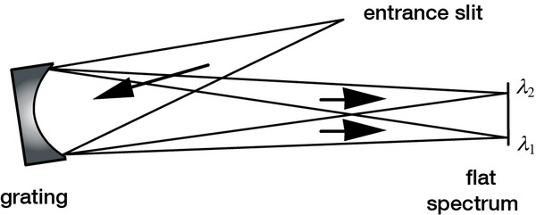
One of the advantages of changing the groove pattern (as on a first- or second- generation holographic grating or a VLS grating) is that the focal curves can be modified, yielding grating mounts that differ from the classical ones. A logical improvement of this kind on the Rowland circle spectrograph is the flat-field spectrograph, in which the tangential focal curve is removed from the Rowland circle and rendered nearly linear over the spectrum of interest (see Figure 7-7). While a grating cannot be made that images a spectrum perfectly on a line, one that forms a spectrum on a sufficiently flat surface is ideal for use in linear detector array instruments of moderate resolution. This development has had a significant effect on spectrograph design.
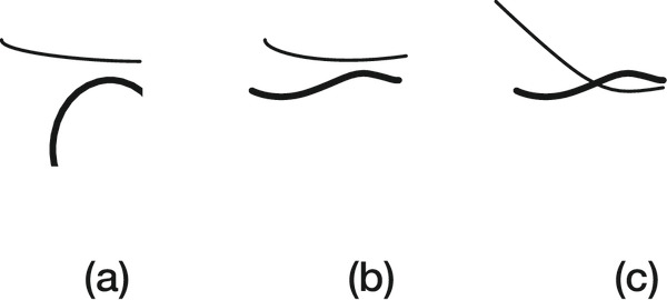
The relative displacement between the tangential and sagittal focal curves can also be reduced via VLS or interferometric modification of the groove pattern. In this way, the resolution of a flat-field spectrometer can be maintained (or improved) while its astigmatism is decreased; the latter effect allows more light to be transmitted through the exit slit (or onto the detector elements). An example of the process of aberration reduction is shown in Figure 7-8.
Imaging spectrographs and monochromators
Concave gratings may also be used in imaging spectrographs,which are instruments for which a spectrum is obtained for different spatial regions in the object plane. For example, an imaging spectrometer may generate a two-dimensional spatial image on a detector array, and for each such image, a spectrum is scanned (over time); alternatively, a spectrum can be recorded for a linear slice of the image, and the slice itself can be moved across the image to provide the second spatial dimension (sometimes called the “push broom” technique).
Constant-deviation monochromators
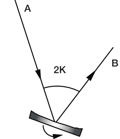
In a constant-deviation monochromator, the angle 2K between the entrance and exit arms is held constant as the grating is rotated (thus scanning the spectrum; see Figure 7-9). This angle is called the deviation angle or angular deviation (AD). While plane or concave gratings can be used in constant-deviation mounts, only in the latter case can imaging be made acceptable over an entire spectrum without auxiliary focusing optics.
The Seya-Namioka monochromator is a very special case of constant-deviation mount using a classical spherical grating, in which the deviation angle 2K between the beams and the entrance and exit slit distances (r and r') are given by
2K = 70°30', r = r' = Rcos(70°30'/2) (7-29)
where R is the radius of the spherical grating substrate. The only moving part in this system is the grating, through whose rotation the spectrum is scanned. Resolution may be quite good in part of the spectrum, though it degrades farther from the optimal wavelength; astigmatism is high, but at an optimum. Replacing the grating with a classical toroidal grating can reduce the astigmatism, if the minor radius of the toroid is chosen judiciously. The reduction of astigmatism by suitably designed holographic gratings is also helpful, though the best way to optimize the imaging of a constant-deviation monochromator is to relax the restrictions given by Eqs. (7-29) on the use geometry.
For footnotes and additional insights into diffraction grating topics like this one, download our free MKS Diffraction Gratings Handbook (8th Edition)
Download a Handbook