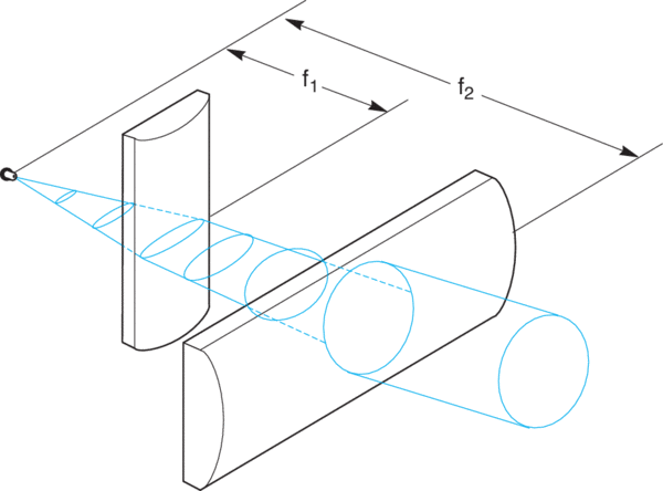
A few observations will guide the selection and placement of the lenses:
1) To achieve a symmetrical beam shape, the ratio of the focal length of the two lenses should be approximately equivalent to the ratio of the beam divergences:
θ1/θ2 = 10°/40° = f1/f2
2) First, to order, the laser diode is approximated by a point source, so the lenses should be placed at a distance equal to their respective focal lengths from the source to create a collimated output.
3) The principal planes of the two lenses should be spaced at a distance apart equal to the difference of their focal lengths f2 - f1. The actual spacing between plano surfaces of the lenses is BFL2 - BFL1. As with spherical lenses the convex surfaces should face the collimated rays to minimize aberrations.
4) Because of the rapid divergence of the laser diode beam, care must be taken to make sure the beam width at each lens does not exceed the lens clear aperture. Since each lens is placed one focal distance from the laser diode, the maximum beam width at each lens (d1 and d2) can be determined from the following equations:
d1 = 2f1(tan (θ2/2)), and d2 = 2f2(tan (θ1/2))
For this example a convenient choice of lenses is Newport CKX012 (f1 = 12.7 mm, BFL1 = 7.49 mm) and CKX050 (f2 = 50.2 mm, BFL2 = 46.03 mm). The nominal spacing between plano surfaces of the lenses is BFL2 - BFL1 = 38.54 mm. The beam diameter at the first lens is
d1 = 2 x 12.7 mm x tan(20°) = 9.2 mm
The beam diameter at the second lens is
d2 = 2 x 50.2 mm x tan(5°) = 8.8 mm
so a slight asymmetry remains, but a substantial improvement has been achieved with a simple arrangement of standard lenses.
 Over 8,000 products in-stock! & FREE 2-Day shipping on all web orders!* Learn More FREE T-Shirt with orders $250+ Details

 Ultra-High Velocity