Beam Shaping with Cylindrical Lenses
Cylindrical Lenses focus or expand light in one axis only. They can be used to focus light into a thin line in optical metrology, laser scanning, spectroscopic, laser diode, acousto-optic, and optical processor applications. They can also be used to expand the output of a laser diode into a symmetrical beam.
Generating a Line of Light from a Collimated Laser
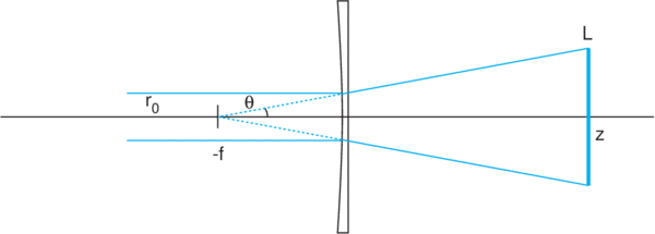
A common application of cylindrical lenses is shown in Figure 1. A collimated laser beam of radius r0 is incident upon a cylindrical plano-concave lens of focal length -f. In this figure, the radius of the laser beam is exaggerated for clarity. The laser beam will expand with a half-angle θ of r0/f. The laser beam will appear to be expanding from a virtual source placed a distance f behind the lens. At a distance z after the lens, there will be a line with thickness 2r0 (ignoring expansion of the Gaussian beam) and length
L = 2 (r0/f)(z+f)
If z is large compared to f, then we have an expansion ratio that is very close to z/f. This is not an imaging problem; we are projecting the laser beam into a line at a particular distance. The length of the line is simply proportional to z.
If the thinnest possible line is required, then a second lens, this one a cylindrical plano-convex lens of focal length ~ z, can be inserted into the system just before or after the plano-concave lens. When oriented on the orthogonal axis, it will focus the laser at the screen onto which the line is projected
In some cases a sheet of light is required for an application. The projected beam of Figure 1 can be thought of as a sheet of light, but note that the sheet is not square or rectangular. The sheet that is available for use is the isosceles triangle formed by the projected line at the screen and the maximum rays formed at the angles given by θ.
Circularizing the Beam from a Laser Diode
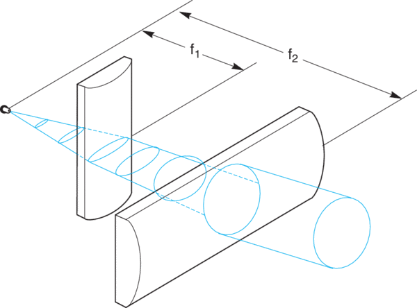
The output of a laser diode diverges in an asymmetrical pattern, making collimating the beam a challenge. Cylindrical lenses can be used to circularize the beam. Consider a laser diode with beam divergence of θ1 x θ2 = 10°x 40°. Any attempt to collimate this beam with spherical optics would result in collimation in one direction only, with a diverging or converging beam in the other direction. With cylindrical optics the problem can be approached as two one dimensional problems. The simplest solution would be to collimate the beam in one dimension with a single cylindrical lens, then collimate the orthogonal dimension with a second cylindrical lens (see Figure 2).
A few observations will guide the selection and placement of the lenses:
1) To achieve a symmetrical beam shape, the ratio of the focal length of the two lenses should be approximately equivalent to the ratio of the beam divergences:
θ1/θ2 = 10°/40° = f1/f2
2) First, to order, the laser diode is approximated by a point source, so the lenses should be placed at a distance equal to their respective focal lengths from the source to create a collimated output.
3) The principal planes of the two lenses should be spaced at a distance apart equal to the difference of their focal lengths f2 - f1. The actual spacing between plano surfaces of the lenses is BFL2 - BFL1. As with spherical lenses the convex surfaces should face the collimated rays to minimize aberrations.
4) Because of the rapid divergence of the laser diode beam, care must be taken to make sure the beam width at each lens does not exceed the lens clear aperture. Since each lens is placed one focal distance from the laser diode, the maximum beam width at each lens (d1 and d2) can be determined from the following equations:
d1 = 2f1(tan (θ2/2)), and d2 = 2f2(tan (θ1/2))
For this example a convenient choice of lenses is Newport CKX012 (f1 = 12.7 mm, BFL1 = 7.49 mm) and CKX050 (f2 = 50.2 mm, BFL2 = 46.03 mm). The nominal spacing between plano surfaces of the lenses is BFL2 - BFL1 = 38.54 mm. The beam diameter at the first lens is
d1 = 2 x 12.7 mm x tan(20°) = 9.2 mm
The beam diameter at the second lens is
d2 = 2 x 50.2 mm x tan(5°) = 8.8 mm
so a slight asymmetry remains, but a substantial improvement has been achieved with a simple arrangement of standard lenses.