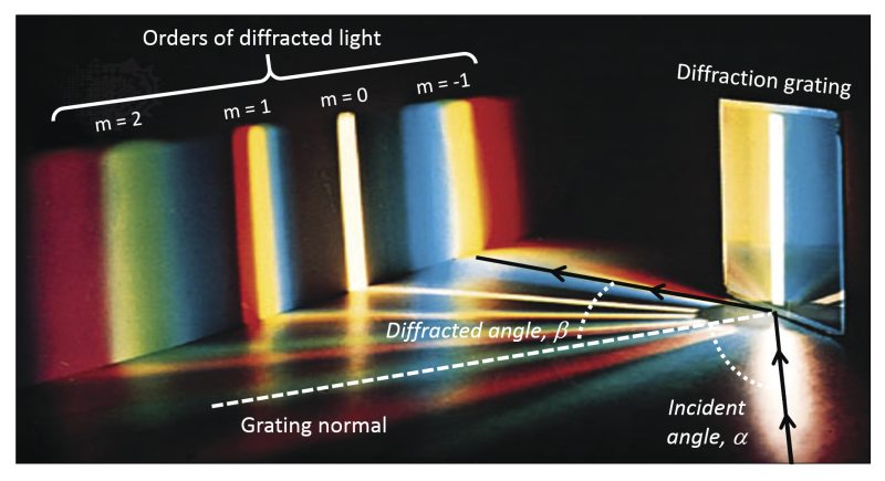
Diffraction Grating Physics
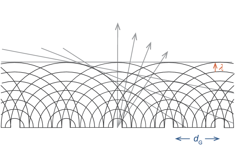
When light encounters an obstacle such as an opaque screen with a small opening (or aperture), the intensity distribution behind the screen can look much different than the shape of the aperture that it passed through. Since light is an electromagnetic wave, its wavefront is altered much like a water wave encountering an obstruction. This diffraction phenomenon occurs because of interference (see Laser Light Characteristics on coherence for details) between different portions of the wavefront. The resulting intensity distribution is called a diffraction pattern. Similarly, when light passes through an opaque screen consisting of multiple elongated apertures (or slits) with a fixed spacing between them, the emerging wavefronts constructively interfere to produce a diffraction pattern with intensities peaked in certain directions as shown in Figure 1. These directions are strongly dependent on both the slit spacing and wavelength of the incident light. Consequently, surfaces with well-defined slit locations can be used to direct light of certain wavelengths into specific directions.
Diffraction of monochromatic light with wavelength . from a series of apertures with a spacing dG
Figure 1. Diffraction of monochromatic light with wavelength . from a series of apertures with a spacing dG. The angled lines indicate regions of constant phase while arrows denote directions of intensity peaks in the diffraction pattern.
A diffraction grating is essentially a multi-slit surface. It provides angular dispersion, i.e., the ability to separate wavelengths based on the angle that they emerge from the grating. Gratings can be transmissive, like the multi-slit aperture, but they can also be reflective where the grooved surface is overcoated with a reflecting material such as aluminum. A typical diffraction grating (see Figure 2) consists of a large number of parallel grooves (representing the slits) with a groove spacing (denoted dG, also called the pitch) on the order of the wavelength of light. This is more commonly reported as the groove density (G), which is the reciprocal of dG, e.g., typical gratings have G values between 30 and 5000 grooves per mm. The groove spacing determines the angles at which a single wavelength will constructively interfere to form diffracted orders (see below), which are equivalent to the intensity peaks shown in Figure 1. In addition to the spacing of the grooves, the groove profile (see Figure 2) plays a key role in the performance of a grating. When monochromatic light strikes a grating, a fraction of it is diffracted into each order (termed its efficiency). Maximizing the efficiency into a single order, typically the first order, is often desired to ensure increased light collection. To optimize this efficiency for a single wavelength, a procedure known as blazing is performed. This involves modifying the groove profile, including facet angles, shapes and/or depths. The blaze wavelength is the wavelength for which the grating is most efficient.
Depictions of top-down view of diffraction grating showing groove pattern and side view showing different groove profiles
Figure 2. Depictions of top-down view of diffraction grating showing groove pattern (left, top) and side view showing different groove profiles (left, bottom). Scanning electron microscope image of diffraction grating (right).

Grating Equation

The basic grating equation determines the discrete directions into which monochromatic light of wavelength λ is diffracted. The equation is shown below:
The basic grating equation
Figure 3 illustrates this diffraction. Light of wavelength λ is incident at an angle α and diffracted by the grating (with a groove spacing dG) along a set of angles βm. These angles are measured from the grating normal, which is shown as the dashed line perpendicular to the grating surface at its center. If βm is on the opposite side of the grating normal from α, its sign is opposite. In the grating equation, m is the order of diffraction, which is an integer. For the zeroth order (m = 0), α. and β0 are equal and opposite, resulting in the light simply being reflected, i.e., no diffraction. The sign convention for m requires that it is positive if the diffracted ray lies to the left (counter-clockwise side) of the zeroth order and negative if it lies to the right (the clockwise side). When a beam of monochromatic light is incident on a grating, the light is simply diffracted from the grating in directions corresponding to m = -2, -1, 0, 1, 2, 3, etc. When a beam of polychromatic light is incident on a grating, then the light is dispersed so that each wavelength satisfies the grating equation as shown in Figure 3. Usually only the first order, positive or negative, is desired and so higher order wavelengths may need to be blocked. In many monochromators and spectrographs, a constant-deviation mount is used where the wavelength is changed by rotating the grating around an axis while the angle between the incident and diffracted light (or deviation angle) remains unchanged.
Polychromatic light diffracted from a grating
Figure 3. Polychromatic light diffracted from a grating.

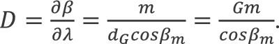
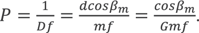
Dispersion, Bandpass, and Resolution

By fixing the incidence angle α in the grating equation and differentiating with respect to λ, the angular dispersion (D) or change in diffraction angle per unit wavelength can be determined as:

Angular dispersion per unit wavelength equation
For a given order m, D represents the ability to discriminate between signals at different wavelengths and increases as the groove density (G) increases. Once a grating is incorporated into a spectrometer with an effective focal length (f, see below for details), the linear dispersion of the system is the product of D and f. In practice, the reciprocal linear dispersion (sometimes called the plate factor P), is more often considered, where:
Plate factor equation
P is a measure of the change in wavelength (in nm) for a given lateral distance (in mm) and can be used to determine the bandpass and resolution of a spectrometer. The bandpass is the width of the spectrum passed by a spectrometer when illuminated by light with a continuous spectrum. In a monochromator, the bandpass is given by the product of P and the slit width. Reducing the width of the slit until a limiting bandpass is reached gives the resolution of the instrument. In spectral analysis, resolution is a measure of the ability of the instrument to separate two spectral lines that are close together. Figure 4 shows the impact of slit width reduction on the ability to resolve sharp spectral lines from a lamp source. The monochromator resolution is also affected by aberrations in the optical system and by proper grating illumination. Minimizing these contributions ensures that the resolution is determined mainly by P and the slit width. Spectrographs have a bandpass and resolution that are mainly dictated by the detector parameters (see below).
Spectra of an incoherent lamp source when passed through a monochromator with a value of P = 13.2 nm/mm
Figure 4. Spectra of an incoherent lamp source when passed through a monochromator with a value of P = 13.2 nm/mm. Reducing the slit width from 760 µm (left) to 120 µm (right) results in an improved spectral resolution from 10.1 nm to 1.6 nm.

Types of Gratings

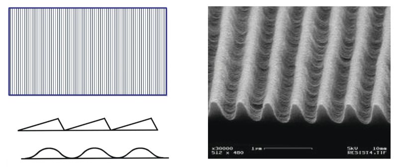
Gratings are produced by two methods, ruling and holography. A high-precision ruling engine creates a master grating by burnishing grooves with a diamond tool against a thin coating of evaporated metal applied to a surface. Replication of the master grating enables the production of ruled gratings, which comprise the majority of diffraction gratings used in dispersive spectrometers. These gratings can be blazed for specific wavelengths, generally have high efficiency, and are often used in systems requiring high resolution. Echelle gratings are a type of ruled grating that are coarse, i.e., low groove density, have high-blaze angles, and use high diffraction orders. The virtue of an echelle grating lies in its ability to provide high dispersion and resolution in a compact system design. Overlapping of diffraction orders is an important limitation of echelle gratings requiring some type of order separation typically provided by a prism or another grating. Holographic gratings are created using a sinusoidal interference pattern which is etched into glass. These gratings have lower scatter than ruled gratings, are designed to minimize aberrations, and can have high efficiency for a single plane of polarization. Gratings can be reflective or transmissive, and the surface of a grating can either be planar or concave. Planar gratings generally give higher resolution over a wide wavelength range while concave gratings can function as both a dispersing and focusing element in a spectrometer.


MKS Semiconductor Handbook Cover

For additional insights into photonics topics like this, download our free MKS Instruments Handbook: Principles & Applications in Photonics Technologies

Request a Handbook