Compare Model Drawings, CAD & Specs Availability Price
Cylindrical Lens, Plano-Convex, UVFS, 12.5 mm, 100 mm FL, 245-440 nm
Cylindrical Lens, Plano-Convex, UVFS, 25 mm, 50 mm FL, 245-440 nm
Cylindrical Lens, Plano-Convex, UVFS, 25 mm, 75 mm FL, 245-440 nm

Specifications

  • Lens Type
    Cylindrical
  • Lens Shape
    Plano-Convex
  • Lens Material
    UV Fused Silica
  • Antireflection Coating
    245-440 nm
  • Coating Type
    Broadband UV
  • Coating Code
    AR.10
  • Damage Threshold
    2 J/cm2, 10 nsec pulses, 10 Hz at 355 nm
  • Surface Quality
    40-20 scratch-dig
  • Surface Flatness
    λ/2-λ/4
  • Focal Length Tolerance
    ±2.0%
  • Clear Aperture
    ≥central 80% of dimensions

Features

UV Fused Silica Substrates for UV, Laserline & Broadband Applications

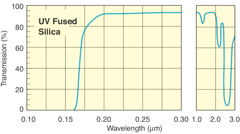
UV Grade Fused Silica is synthetic amorphous silicon dioxide of extremely high purity providing maximum transmission from 195 to 2100 nm. This non-crystalline, colorless silica glass combines a very low thermal expansion coefficient with good optical qualities, and excellent transmittance in the ultraviolet region. Transmission and homogeneity exceed those of crystalline quartz without the problems of orientation and temperature instability inherent in the crystalline form. It will not fluoresce under UV light and is resistant to radiation. For high-energy applications, the extreme purity of fused silica eliminates microscopic defect sites that could lead to laser damage. For more information, refer to our optical materials Technical Note

Mount in Standard Lens Mounts

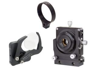
These round plano-convex cylindrical lenses are designed to mount into standard optical lens mounts.  The round optic shape provides many more mounting options compared to rectangular cylindrical lenses that require special cylindrical lens mounts for mounting.

Ultraviolet Antireflection Coating

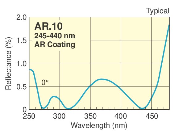
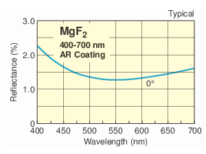
Our AR.10 broadband multilayer antireflection coating markedly improves the transmission efficiency of UV lenses in the 245 to 440 nm ultraviolet region.

Circularize a Laser Diode Beam Profile

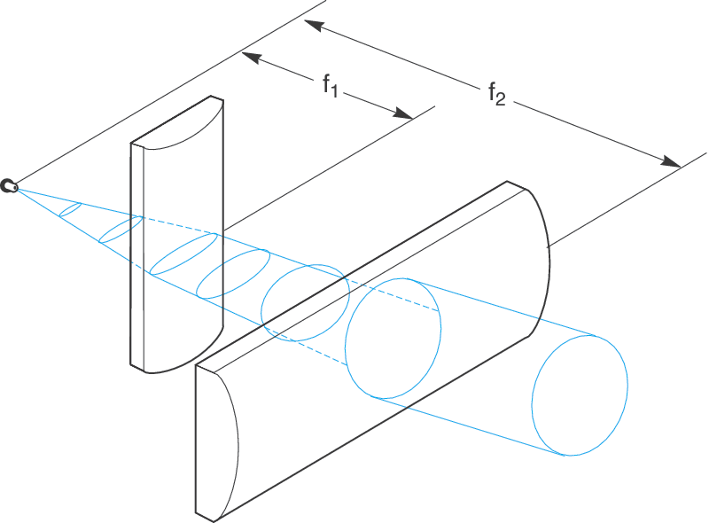
In a typical laser diode (a P-i-N diode), electrical current flows vertically between contacts on top of and below the semiconductor material substrate. Charge carrier combination and the resulting light emission occurs in the intrinsic region between the doped electrodes. A horizontal optical cavity is formed by cleaving the substrate and polishing the side faces. Fresnel surface reflections at these faces create optical feedback resulting in a lasing effect. Light emitted from a rectangular aperture typically takes on an elliptical beam profile with angle θ1 and θ2 along the major and minor axes. Two cylindrical lenses with focal lengths f2/f1 = θ1/θ2, each positioned their focal length away from the laser diode, may be used to produce a circular collimated beam output.