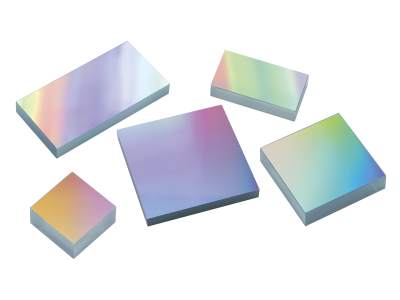
Specifications

  • Grating Type
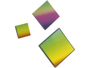
    Plane Ruled
  • Material
    Float Glass
  • Coating Type
    Aluminum
  • Thickness
    6 mm

Features

Plane Ruled Diffraction Grating Construction

In general, for ruled diffraction gratings the groove spacing determines the diffraction angles, and the groove depth and blaze angle determines how diffracted energy is distributed between diffraction orders. Designed for first order Littrow use, Newport’s Plane Ruled Reflection Gratings are blazed to achieve extremely high single-order diffraction efficiency at particular design wavelengths. At Newport, we have three ruling engines in full-time operation, each producing high-quality master gratings each year. These ruling engines provide gratings with triangular groove profiles, very low Rowland ghosts, and high resolving power. Mechanically ruled, individual grooves are burnished with a diamond tool against a thin coating of evaporated metal. Utilizing a high fidelity cast replication process, developed and enhanced through years of research and manufacturing experience, we have the ability to provide duplicates of master gratings that equal the quality and performance of the master grating.

Optimum Diffraction Grating Orientation

Plane Ruled Diffraction Gratings are most efficient when used near the design wavelength in the Littrow configuration, that is aligned so that the diffraction angle of the dominant diffraction order is coincident with the input beam, effectively behaving as a retroreflector at a specific wavelength. For blazed gratings, maximum efficiency occurs for wavelengths that the Littrow condition at the angle normal to the blazed grating facets. As ruled blaze gratings are asymmetric, correct orientation is indicated with an arrow marking on the size of the substrate. The arrow is on the side of the substrate perpendicular to the ruled grooves, and points toward the steeper edge of the triangular groove profile. Equivalently, the arrow points away from the grating normal toward the facet normal. The arrow should point toward the incident (and diffracted) beam.

Diffraction Grating Physics

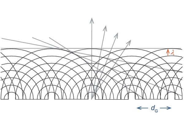
When light encounters an obstacle such as an opaque screen with a small opening (or aperture) the intensity distribution behind the screen can look much different than the shape of the aperture that it passed through. Since light is an electromagnetic wave, its wavefront is altered much like a water wave encountering an obstruction. This diffraction phenomenon occurs because of interference between different portions of the wavefront. The resulting intensity distribution is called a diffraction pattern. Similarly, when light passes through an opaque screen consisting of multiple elongated apertures (or slits) with a fixed spacing between them, the emerging wavefronts constructively interfere to produce a diffraction pattern with intensities peaked in certain directions as shown in the figure. These directions are strongly dependent on both the slit spacing and wavelength of the incident light. Consequently, surfaces with well-defined slit locations can be used to direct light of certain wavelengths into specific directions.

Diffraction of monochromatic light with wavelength λ from a series of apertures with a spacing dG. The angled lines indicate regions of constant phase while arrows denote directions of intensity peaks in the diffraction pattern.

The Grating Equation

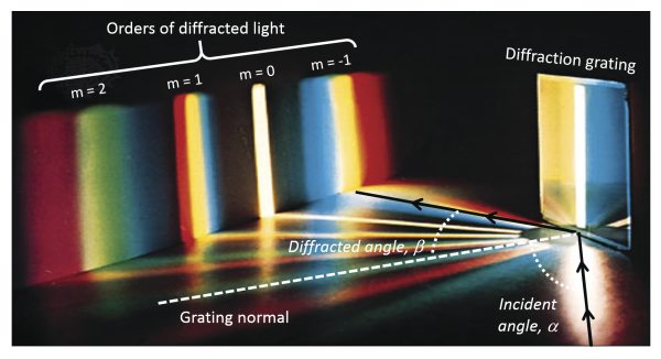
Polychromatic light diffracted from a grating.

The basic grating equation determines the discrete directions into which monochromatic light of wavelength λ is diffracted. The equation is shown below:

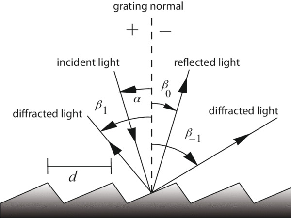
mλ = dG (sinα + sinβm)

The above figure illustrates this diffraction. Light of wavelength λ is incident at an angle α and diffracted by the grating (with a groove spacing dG) along a set of angles βm. These angles are measured from the grating normal, which is shown as the dashed line perpendicular to the grating surface at its center. If βm is on the opposite side of the grating normal from α, its sign is opposite. In the equation, m is the order of diffraction, which is an integer. For the zeroth order (m = 0), α and β0 are equal and opposite, resulting in the light simply being reflected, i.e., no diffraction. The sign convention for m requires that it is positive if the diffracted ray lies to the left (counter-clockwise side) of the zeroth order and negative if it lies to the right (the clockwise side). When a beam of monochromatic light is incident on a grating, the light is simply diffracted from the grating in directions corresponding to m = -2, -1, 0, 1, 2, 3, etc. When a beam of polychromatic light is incident on a grating, then the light is dispersed so that each wavelength satisfies the grating equation as shown in the figure. Usually only the first order, positive or negative, is desired and so higher order wavelengths may need to be blocked. In many monochromators and spectrographs, a constant-deviation mount is used where the wavelength is changed by rotating the grating around an axis while the angle between the incident and diffracted light (or deviation angle) remains unchanged.

Ultrafast Pulse Amplification

Pairs of identical diffraction gratings that are tuned to the polarization and output wavelengths of a laser may be used to temporally compress ultrafast laser pulses, greatly increasing the peak power. When a spectrally broad laser pulse is incident on a diffraction grating, the various wavelength components will disperse, or diffract in different directions. If this pulse has its wavelength chirped (i.e. its frequency progressively increases during the length of the pulse) the first grating will diffract the leading portion of the pulse (consisting of longer wavelengths) at a greater angle compared to the trailing portion of the pulse (consisting of shorter wavelengths). When the light reaches the second grating with same periodicity the dispersion will be reversed from symmetry and the light will be collimated. Light from the leading edge of the pulse will travel a longer optical path through the pair of gratings, requiring more travel time. If the separation between the gratings is chosen so that the travel time difference matches the pulse duration, the laser power will be compressed into a nearly instantaneous pulse.

Dual Grating Compressor Setup Example

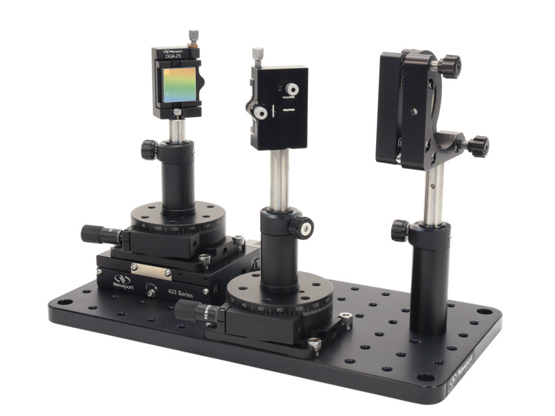
Two gratings and a mirror are used in the classic Mourou-Strickland setup, to fashion a basic ultrafast beam compressor. Gratings are typically chosen when a large amount of dispersion is required and can be used in higher energy applications because they are reflective. See the parts list of the shown setup example below.

Part No Description Quantity
Grating of Your Choice 2
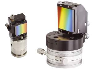
DGA-25 Diffraction Grating Mount 2
481-A Rotation Stage 2
433 Linear Stage 1
20D20ER.2 2 in. Silver Mirror 1
M2 Mirror Mount 1
SP-2 Optical Post, 2 in. 1
SP-3 Optical Post, 3 in. 2
VPH-2 Post Holder, 2 in. 2
VPH-3 Post Holder, 3 in. 1

Low Rowland Ghosting

By incorporating interferometric monitoring into the process of fabricating ruled grating masters, Newport is able to minimize irregularities in grating period and position. This greatly reduces the effect of ghosts, or secondary spectra, or energy into undesired wavelength-angle combinations due to irregularities in surface periodicity. Ghosts that are close to and symmetric about the parent diffracted line are called Rowland ghosts, due to low spatial frequency content (or periodicities much larger than the groove spacing). Lyman ghosts are farther from the parent line and are caused by unwanted periodicities on the order of the groove spacing. Both Rowland and Lyman ghosts follow the grating equation, although Rowland ghosts are typically more problematic for spectroscopy applications. Newport's process is designed specifically to minimize the effects of Rowland ghosting.

Handling Diffraction Gratings

As Newport's Plane Ruled Reflection Gratings feature a delicate, precisely patterned reflective surface, the surface cannot be touched with without damaging the fringe pattern and potentially seriously degrading the optical performance. Damage to the grating can take the form of contamination or distortion of the microscopic groove profile. Damage to this microscopic groove profile is, unfortunately, irreversible. The resin layer like modeling clay, will retain a permanent imprint. Contamination with finger oils, moisture, etc. is also often permanent. Because of the sensitive nature of the grating groove profile, it is imperative that the user take precautions in handling gratings. Do not touch the surface of the grating; handle the grating by the edges and always wear gloves or finger cots. Use a non-contact cleaning method such as dry, compressed air or a dust bulb to remove excess dust from a grating.

Float Glass Substrate

Float glass is made by floating molten glass over a bed of molten metal. While this is a low cost material that is used in commercial windows, the production method yields a very flat surface of uniform thickness making it a good choice for optics.

Special Orders

In addition to the gratings listed here, special order gratings for various applications including OEM may also be available. Contact Newport's Richardson Gratings for more information.